
Correlation transit-time technology is ideal for flare gas flow measurement
The correlation transit-time technique has distinct advantages over other methods of flare gas flow measurement, and it is used to solve a variety of difficult problems. Typically, gas in flare stacks, headers or laterals is a mixture of components from different sources. Flow rate in flare systems may be unsteady or even bidirectional. Pulsating pressure, varying composition and temperature, harsh environment, and wide flow range further complicate the measurement. The GF868 is designed for superior performance under these conditions.
Patented molecular weight measurement method
The DigitalFlow GF868 uses a patented method for calculating the average molecular weight of hydrocarbon mixtures. This proprietary algorithm extends the range for measuring average molecular weight, while improving accuracy and compensating for non-hydrocarbon gases better than ever before possible. Higher accuracy mass flow data and more precise knowledge of flare gas composition can improve the efficiency of plant operation, enabling correct metering of steam injection at the flare tip, rapid troubleshooting of leaks into the flare stream, early detection of process control problems, and accurate plant balance.
Identify leak sources, reduce steam usage and improve plant material balance
Leaks and excess steam delivery are two major causes of loss of product and energy. Reducing them immediately improves the overall efficiency in refinery and chemical plant operation. Payback for the entire DigitalFlow GF868 installation usually occurs within a matter of months
The DigitalFlow GF868 can help save millions of dollars in reduced losses.
Once the sound speed of the gas has been determined by the DigitalFlow GF868, its on-board computer uses temperature and pressure inputs in conjunction with the sound speed to calculate instantaneous average molecular weight and mass flow rate of the gas. These parameters are used to help identify sources of leaks into the flare system. Detection of even a small increase in flow rate into the flare system may indicate a leak source such as partially unseated relief valve. An accompanying change in the average molecular weight of the flare gas may be used to help locate the leak source. Quick identification and elimination of leak sources into the flare system saves significant amounts of potentially lost energy and product. Mass flow rate may be used to perform a mass balance calculation and to control flare tip steam injection. By knowing the exact amount of gas flow and average molecular weight in the flare stack, delivery of the correct amount of steam required at the flare tip can be accurately controlled. Steam usage can be reduced while maintaining compliance with pollution control regulations.
Rack Mount LCD Display Replacement
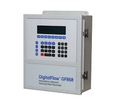
The Model GF868 measurements are displayed on a two-pane LCD graphic display panel. The LCD display normally provides years of dependable service, but it is field-replaceable when necessary
To replace the LCD display, refer to Figure B-2 on page B-11 and complete the following steps:
1. After disconnecting the main power to the meter, remove the top panel from the enclosure by removing the four screws indicated.
2. Using a 3/16 in. nutdriver, remove the four nut/washer sets that secure the display shroud to the inside of the front panel. Pull the display shroud off its mounting studs.
3. Using a 1/4” nutdriver, remove the four standoffs that secure the LCD display assembly to the front panel. Pull the LCD display assembly off its mounting studs.
4. Place the new display in the enclosure and replace the circuit board connections of the data and power cables of the old display with those of the new display. Be sure to orient the new cables in the same way as the old ones, when making the connections to the printed circuit board. Remove and discard the old LCD display.

5. Place the new LCD display assembly over the mounting studs on the front panel and fasten it in place with the four standoffs. Make sure that the LCD display assembly is oriented with the cables pointing toward the left side (away from the keypad) of the meter
6. Position the LCD display cables between the two mounting studs, and install the display shroud over the mounting studs. The top and bottom edges of the shroud are bent at a 90° angle to the main surface, and these edges must face inwards toward the display assembly.
7. Fasten the display shroud to the front panel with the four sets of nuts/washers.
8. After checking for any loose hardware that may have fallen into the enclosure, reinstall the top panel on the meter and secure the panel in place with the four screws previously removed.
The Model GF868 flowmeter may now be placed back into service. Reconnect the main power and resume taking measurements.
Note: Be sure to record the LCD Display replacement in Appendix A, Service Record.
Related product recommendations:
GE IS200JPDBG1A
GE IS200EDISG1A
GE IS400TDBTH6A
GE IS200TCATH1ABA
GE IS220YAICS1A-L
GE IS200TRPGH1BDD
GE IS200TSVCH1ADC
GE IS200TTURH1CCC
DS3800NB1F1B1A GE
IS200WCSAS1A
IS220YSILS1A
IS200TCSAS1A
IS200WNPSS1A
IS41yJPDDG2a
IS41yJPDDG3A
IS40yJPDGH1A
IS411JPDHG1A
IS4210UCSBH4A
MVR1600-4601
MVR1600-4601-A
more……
I am truly thankful to the owner of this web site who has shared this fantastic piece of writing at at this place.
Pretty! This has been a really wonderful post. Many thanks for providing these details.
Nice post. I learn something totally new and challenging on websites
For the reason that the admin of this site is working, no uncertainty very quickly it will be renowned, due to its quality contents.
Great information shared.. really enjoyed reading this post thank you author for sharing this post .. appreciated
Nice post. I learn something totally new and challenging on websites
Pretty! This has been a really wonderful post. Many thanks for providing these details.