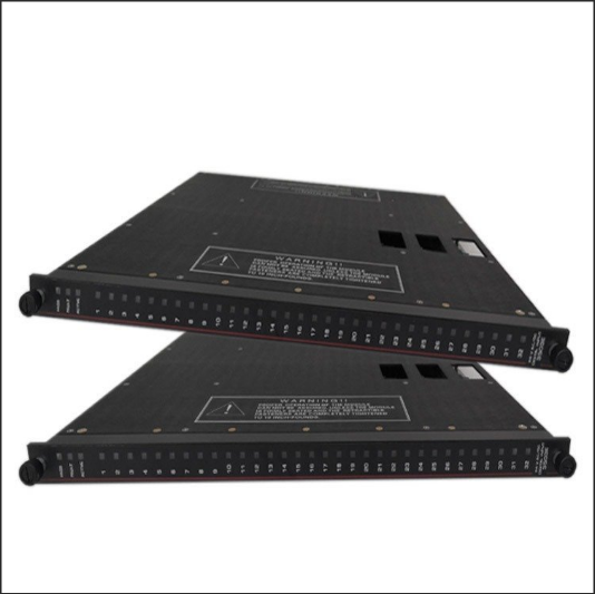
The TRICONEX TMR digital input module 3503E is a core component of Schneider Electric’s Tricon safety system. Designed for high-reliability industrial scenarios (such as ESD, F&G, and nuclear power safety systems), it utilizes a triple modular redundant (TMR) architecture and a 2oo3 voting mechanism to ensure that single-point failures do not cause system malfunctions.
I. Core Architecture and Technical Features
TMR Redundancy Design: Utilizing a triple modular redundant (TMR) architecture, three independent input circuits operate in parallel. A 2oo3 (two out of three) voting mechanism ensures high safety, preventing single-point failures from causing system malfunctions.
Wiring: Supports single-ended and differential inputs (requires configuration), with a removable terminal block for easy maintenance. Dry contacts (passive) connect directly to switches/relays, while wet contacts (active) require an external 24V power supply (such as a proximity switch).
Status Indicator: A dual-color LED (red/green) displays signal status on each channel, and module-level indicators (Power, Active, and Fault) monitor overall operation.
Supported Input Types:
Dry Contact: Directly connect to switches or relay contacts (passive signals).
Wet Contact: Requires an external 24V power supply (e.g., proximity switches or sensors). Supports single-ended or differential inputs (configuration required).
Status Indicator: A dual-color LED (red/green) displays status for each channel, and module-level indicators (Power, Active, and Fault) provide real-time operational status feedback.
Safety Certification: Compliant with IEC 61508 SIL 3 and TÜV certification, suitable for safety systems such as SIS/ESD/F&G.
II. Installation and Configuration Steps
Physical Installation:
Adopts standard DIN rail mounting, complies with DIN EN 50022 specifications, and features an IP30 aluminum enclosure.
Power supply redundancy supports a wide DC 9-36V input voltage range, reverse polarity protection, and 1500V DC isolation.
Wiring Specifications: Comply with electrical installation standards (e.g., yellow-green for grounding and blue/red for control circuits). The terminal block features a removable design for easy maintenance.
Power Requirements: AC 98-162VAC or 195-252VAC, or DC 24V. Check that the PWR light is on. If not, check the power supply voltage, fuse, and frame power module.
System Integration:
Compatible with Tricon v9/v10/v11 control systems, it communicates with the main processor via TriBus and supports data voting and diagnostic information transmission.
Configuration requires EnDM software (Enhanced Diagnostic Monitor) to assign module addresses, set channel parameters, and define fault thresholds.
Signal Wiring:
Single-Ended Input: Connect the common terminal (COM) to 0V and the signal terminal to +24V or a switch. Avoid parallel operation with power lines. Wiring in separate slots or with a separator is recommended.
Differential Input: Requires configuration to improve interference immunity and is suitable for high-noise environments.
Shielding and Grounding: Use shielded cables for analog signals, with the shield grounded at one end (resistance < 1/10 of the shield resistance); route AC/DC output cables separately, away from high-voltage power lines.
III. Maintenance and Diagnosis
Daily Maintenance:
Regular Testing: Perform channel tests every six months to verify input signal accuracy; perform redundant switching tests annually to ensure seamless failover in the event of a fault.
Environmental Monitoring: The module storage environment requires a temperature of 15-35°C and a humidity of 30-70% RH to avoid performance degradation caused by extreme temperatures and humidity.
Indicator Check: The PASS, FAULT, and ACTIVE indicators directly reflect the module’s health and require regular inspections.
Fault Diagnosis Tools:
EnDM Software: Monitors system status in real time, collects and analyzes fault events (such as channel disconnection, short circuit, and power supply abnormality), and supports rapid location and replacement of faulty modules.
Hardware Diagnosis: Initial diagnosis is performed based on the module’s front panel LEDs, relay alarm outputs (such as power failure and fiber link interruption), and fuse status.
IV. Troubleshooting Process
Preliminary Inspection:
Confirm that the power input is normal and that the redundant power supply has switched successfully.
Check for loose wiring and secure terminal block connections.
Observe indicator light status: If the FAULT light is on, use the EnDM software to check the specific fault code.
Software Diagnosis:
Log in to the EnDM software, locate the faulty module and channel, and analyze event logs (e.g., “channel disconnected” or “voting failed”).
Isolate the suspected faulty channel to confirm whether it is a field device issue (e.g., sensor failure).
V. Configuration and System Integration
System Compatibility: Compatible with Tricon v9/v10/v11 safety control systems. Input channel parameters (e.g., signal type, filter settings) must be configured through the main processor.
Diagnostic Function: Supports detection of disconnections, short circuits, and channel faults. Faults activate the module’s Fault light and trigger a chassis alarm. Error codes can be viewed and corrected using the programmer.
Hot Swapping and Maintenance: Hot swapping is supported. Maintenance must adhere to the “channel testing every six months, redundant switching testing annually” cycle. Spare parts must be stored in a controlled temperature and humidity environment (15-35°C, 30-70% RH).
Hardware Handling:
Faulty modules are hot-swappable and can be replaced online. After replacement, parameters must be reconfigured and tested.
If the fault is system-level (such as bus communication interruption), check the TriBus bus connection and main processor status.
V. Application Scenarios and Precautions
Typical Applications: Emergency Shutdown Systems (ESD), Fire and Gas Protection (F&G), Nuclear Power Safety Interlocks, and Critical Process Control in the Petrochemical Industry.
VI. Troubleshooting and Safety Precautions
Common Troubleshooting:
PWR light off: Check the power supply voltage, fuse, and frame power module.
RUN light off: Verify that the programmer is in RUN mode or check for program errors.
BATT light on: Replace the lithium battery to ensure program backup and reloading.
Electromagnetic Interference Protection: Keep away from welding machines and high-power equipment; inductive loads (such as relays) require a parallel RC circuit; use shielded cables for analog signals and ensure proper grounding.
Safety Standards: Strictly adhere to SIL3 safety level requirements and conduct regular functional safety assessments. The system must be TÜV certified to ensure compliance with international safety standards.
Precautions:
Avoid use in environments with strong electromagnetic interference and comply with EMC testing standards (such as EN55022).
Wet contact inputs require a stable external power supply to prevent voltage fluctuations from affecting signal acquisition.
During maintenance, adhere to the “power off before operation” principle to ensure personal and equipment safety.
VII. Typical Application Scenarios
Emergency Shutdown System (ESD): Collects signals from on-site emergency stop buttons, liquid level switches, and other devices to trigger safety interlocks.
Fire and Gas Protection System (F&G): Monitors smoke and flame detector signals and activates firefighting equipment.
Nuclear Power Safety System: Ensures reliable monitoring and control of key process parameters (such as pressure and temperature).
Related product recommendations:
ICS TRIPLEX TC-011-02-2M5
ICS TRIPLEX TC-801-02-4M5
ICS TRIPLEX TC-314-02-2M5
TRICONEX 8405N
TRICONEX 4609
TRICONEX 3805E
TRICONEX 3708EN
More……
The structure of this piece is excellent.
excellent post.Ne’er knew this, appreciate it for letting me know.
I am so happy to read this. This is the type of manual that needs to be given and not the accidental misinformation that is at the other blogs. Appreciate your sharing this greatest doc.