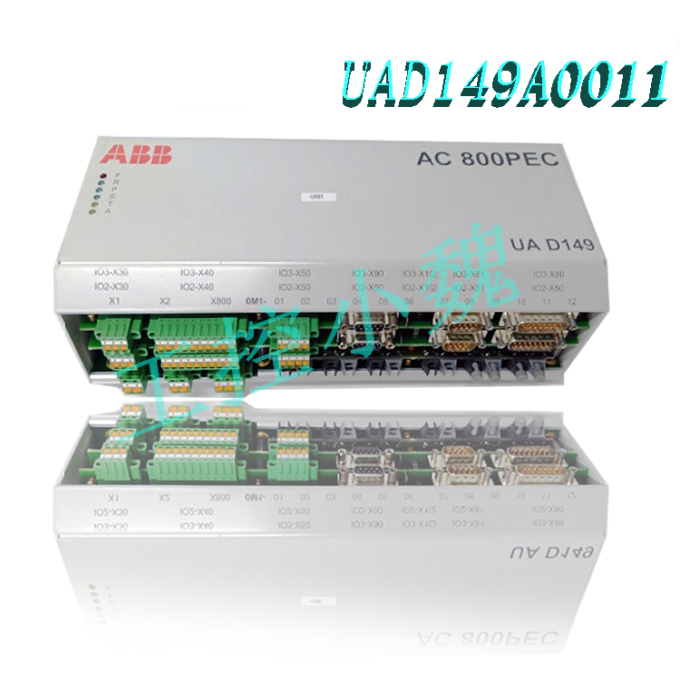
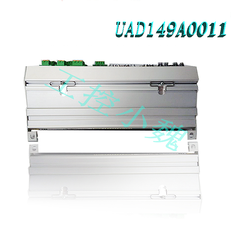
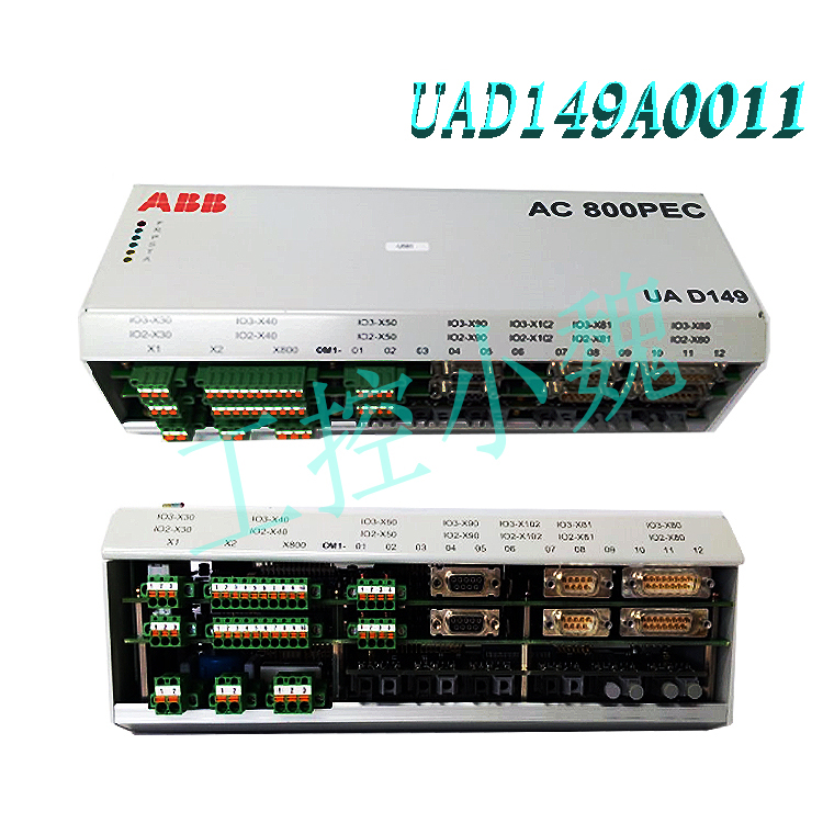
ABB Excitation Control Unit UAD149A0001 3BHE014135R0001 Usage Precautions
I. Electromagnetic Compatibility and Grounding Requirements
Electromagnetic Interference Protection: The equipment is susceptible to electromagnetic interference from motor brush sparks, switch operations, fluorescent lamps, etc., which may lead to communication failures or equipment damage. Shielded cables and proper grounding (e.g., a separate grounding system) are required, and cross-interference with high-frequency signal lines should be avoided. It is recommended to use a dedicated grounding busbar to ensure grounding resistance <1Ω to prevent voltage transients and peak interference.
Shielding and Wiring: Cables must be twisted-pair or shielded, and parallel wiring with power cables should be avoided. In high-frequency environments, cables should be treated as transmission systems to prevent signal reflection and energy coupling. Connectors must maintain good contact to prevent oxidation or loosening that could increase contact resistance.
Grounding Standards: Strictly adhere to industrial grounding standards (e.g., IEC 60068-2-64 vibration resistance, IEC 60068-2-29 shock resistance) to ensure grounding resistance ≤1Ω and avoid ground loop interference. Metal components inside the control cabinet must be equipotentially bonded to prevent malfunctions caused by potential differences.
II. Installation Environment and Physical Requirements
Environmental Adaptability: Operating temperature range -25°C to +70°C, protection rating IP20 (for control cabinet installation). Avoid high humidity, high vibration, and dusty environments to prevent dust accumulation leading to poor heat dissipation or short circuits. Regular dust removal (e.g., quarterly filter cleaning) and checking the cooling fan’s operation are recommended.
Mechanical Installation: Must be fixed to a standard rack, ensuring the seismic design complies with IEC 60068-2-64. Avoid bending cables during installation to prevent stress damage. Redundant modules must be symmetrically arranged to ensure that hot-swapping does not affect system operation.
III. Power Supply and Electrical Connections
Power Supply Specifications: Input voltage 24V DC, redundant power supply (e.g., dual power input) required, supporting hot-swapping. Power cables must be flame-retardant and equipped with overcurrent protection devices (e.g., fuses). Avoid voltage fluctuations exceeding ±10%, otherwise the protection mechanism may be triggered.
Connector Configuration: JP1/JP2 jumpers must be correctly configured according to the system voltage and card group number to ensure correct electrical path. WP3/WP4 jumpers must be connected to P2A-P2B and P1A-P1B with custom buffer capacitors to enhance voltage stability. Connectors should be inspected regularly to prevent oxidation or loosening.
Power Monitoring: Built-in self-test mechanism, providing status codes via Modbus protocol (e.g., error code 2 corresponding to an illegal data address). A power monitoring system needs to be configured to monitor voltage, current, and temperature in real time, and immediately troubleshoot when alarms are triggered.
IV. Maintenance and Fault Diagnosis
Regular Maintenance: Check the power module temperature and output voltage stability monthly, using ABB Engineering Tools for configuration and diagnostics. Monitor status codes via Modbus protocol (e.g., error code 2 corresponding to an illegal data address), and use diagnostic tools for remote monitoring. A comprehensive inspection is recommended every six months, including tightening wiring and cleaning the cooling system.
Troubleshooting: In case of no display, abnormal output, or communication failure, follow the troubleshooting procedure: Check power connections, fuse status, control transformer, and display board; verify communication interface and protocol settings; use professional tools (such as a multimeter) to measure voltage/current, avoiding live operation. For complex problems, contact ABB technical support to avoid non-standard configurations.
V. Safe Operating Procedures
Personnel Qualifications: Installation, operation, and maintenance must be performed by trained and qualified professionals, complying with local safety standards (such as IEC 61010). Power must be disconnected and no voltage confirmed before operation; use insulated tools to prevent electric shock.
Safety Protection: Warning signs must be posted in high-voltage areas; wear protective equipment (such as insulated gloves) during operation. The system must be equipped with an emergency stop button, and its effectiveness must be tested regularly. In case of a fault, follow the principle of “disconnect power before maintenance” to avoid secondary accidents.
Emergency Stop: An emergency stop button must be provided to ensure rapid power disconnection in abnormal situations, preventing equipment damage or personal injury.
VI. System Integration and Compatibility
System Compatibility: Belongs to the ABB AC 800PEC industrial automation system, compatible with AC 800PEC control boards, UFC765AE102, GVC750BE101, and other modules. Supports Modbus, PROFIBUS, Ethernet, and other protocols, allowing seamless integration with PLCs, SCADA systems, and third-party devices (such as Siemens and Honeywell).
Software Configuration: Parameter settings (such as voltage/current range, communication protocol) are performed using ABB Engineering Tools. Full-channel seamless switching and safety preset values are supported. Avoid non-standard configurations (e.g., compatibility with third-party devices needs verification). Refer to the official manual or contact technical support first.
Expansion Limitations: When expanding I/O modules or communication interfaces, compatibility must be verified (e.g., Arduino DUE requires careful evaluation). Non-standard configurations (e.g., overclocking) are prohibited to avoid affecting system stability.
Summary: The UAD149A0001 must operate under strict electromagnetic compatibility, environmental control, power management, maintenance specifications, and safe operation to ensure system stability and equipment lifespan. It is recommended to combine ABB’s official manual with regular training to improve operators’ skills and reduce the risk of malfunctions.
Model recommendation:
UAC389AE02
HIEE300888R0002 UAC389AE02
UAD149A00-0-11
AC800PECUAD149A0011
AC800PECUAD149A0011
UAD149A0011 3BHE014135R0011
UAD154A
UAD154A 3BHE026866R0101
UAD155A0111
UAD155A0111 3BHE029110R0111
PPD517A3011 3BHE041576R3011
PPD517 3BHE041576R3011
3BHE040375R103E PPD115
PPD539A102 3BHE039770R0102
3BHE057901R0101 PCD235
3BHE039724R0C3D PPD513AOC-100440
PCD235C101 3BHE057901R0101
GFD563A102 3BHE046836R0102
GFD233A101 3BHE022294R0101
GFD563A101 3BHE046836R0101
GFD563A102 3BHE046836R0102
GF D563 3BHE046836R010
PPD512 A10-15000 3BHE040375R1023
More……
Thank you for being so generous with your knowledge.
I wasn’t sure what to expect at first, but this turned out to be surprisingly useful. Thanks for taking the time to put this together.
Great post! I’m going to share this with a friend.