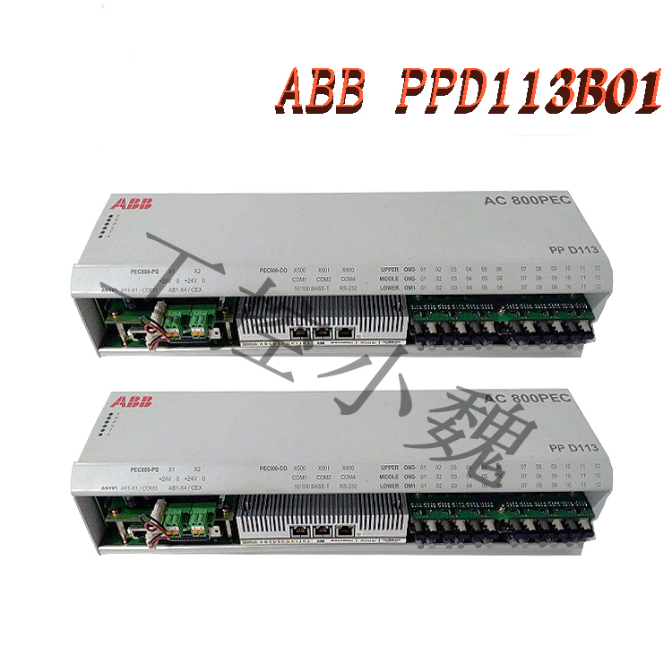
ABB AC 800PEC Control System PPD113B01-25-111000 3BHE023784R2530 Computer Connection and Usage Guide
Core Hardware and Software Requirements
Hardware Interface:
Interface Selection: Connect the controller’s service port (e.g., Service port) or network interface to the computer’s network card using an RJ45 Ethernet cable. For example, if the AC 800PEC controller is equipped with a fiber optic link or Ethernet interface, confirm the module port type (e.g., AnyIO interface, S800 I/O module interface).
Software Tools: ABB official software must be installed, such as Control Builder (programming and configuration), System 800xA (integrated management), ToolboxST (network configuration and diagnostics), or PECView (real-time monitoring).
Step 1: Hardware Connection
Physical Connection
Ethernet Connection: Connect the controller’s Ethernet port (e.g., ENET1) to the computer’s network card using a standard network cable. If the controller has a Service port (e.g., X2), it can be directly connected to the computer for debugging.
Serial Connection: Connect the controller to the computer via an RS232 serial cable. Baud rate, data bits, and other parameters need to be configured (usually 9600bps, 8 data bits, no parity).
Dedicated Interface: If a fiber optic link is involved (such as the AnyIO interface), a dedicated fiber optic patch cord must be used to connect to the I/O module or expansion module.
Power Supply and Grounding
Ensure the controller has a stable power supply (usually 24V DC or 120V AC) and check that the grounding meets industry standards (such as IT/TN systems) to avoid electromagnetic interference.
Step 2: Network and IP Configuration
IP Address Settings
Default IP: The controller’s default IP is usually 192.168.101.111 (confirm with the specific model manual). The computer needs to be configured with an IP address in the same network segment (e.g., 192.168.101.X), with a subnet mask of 255.255.255.0.
DHCP Mode: If the controller supports DHCP, the computer can be set to “Obtain an IP address automatically,” and the controller will assign an address. Static IP: Manually configure the controller IP via ToolboxST or system settings to ensure network connectivity with the computer, HMI, and host computer.
Protocols and Ports
Enable Modbus TCP, EtherCAT, or PROFINET protocols and configure the corresponding ports (e.g., 502, 44818).
If using the IONet interface, configure the IEEE 1588 clock synchronization protocol to ensure the I/O module and controller clock deviation is ≤100μs.
Step 3: Software Configuration and Connection
Software Installation and Licensing
Install Control Builder, System 800xA, or ToolboxST and activate the license (ABB license required).
Add the controller device in the software, enter its IP address or MAC address, and select the corresponding communication protocol.
Connection and Diagnostics
One-Click Connection: In ToolboxST or Control Builder, select “Online” → “One-Click Connection.” The software automatically scans for controllers on the network.
Manual Connection: Enter the controller’s IP address, select the communication protocol (e.g., TCP/IP), and test the connection status (e.g., using the Ping command or software diagnostic tools).
Permission Acquisition: After connection, write access permissions are required (e.g., via HMI or software interface). Click “Agree” to authorize when the controller prompts you.
Step 4: System Debugging and Use
Parameter Configuration
Configure I/O modules (e.g., S800 series), communication interfaces, and control logic (e.g., PID parameters, motion control algorithms) in Control Builder.
Monitor real-time data (e.g., vibration, temperature, speed) through PECView or HMI interface and adjust control strategies.
Testing and Verification
Perform analog signal tests (e.g., 4-20mA current loop) to verify the response of sensors and actuators.
Perform Remote Diagnostics: Remotely access the controller via OPC UA or Web interface to analyze fault logs or update firmware.
Safety and Maintenance
Regularly check the integrity of connectors and cables, clean module dust, and ensure good heat dissipation.
When updating firmware or configuration, follow ABB’s official documentation to avoid unauthorized modifications that could lead to system instability.
Maintenance and Expansion
Module Expansion: Connect more I/O modules (such as the S800 series) via fiber optic links to expand system functionality.
Firmware Update: Update the controller firmware using software tools to fix vulnerabilities or improve performance.
Regular Maintenance: Check connectors and cables for integrity, clean dust from module surfaces, and ensure good heat dissipation.
Common Problem Troubleshooting
Connection Failure: Check for IP address conflicts, firewall blocking, and damage to network cables or interfaces.
Signal Abnormalities: Verify probe coil resistance (5-15Ω) and insulation resistance (>100MΩ), and troubleshoot electromagnetic interference (such as poor grounding or shielding failure).
Access Issues: Ensure the computer user has administrator privileges, or reset access permissions using the controller configuration tool.
Summary: By following four steps—hardware connection, network configuration, software integration, and system debugging—stable connection and use of the ABB AC 800PEC controller and computer can be achieved.
Recommended models:
PFVK 135 3BSE007135R1
PFRL101C 2.0KN 3BSE002964R002
PFSA103B 3BSE002487R1
PFXA401S 3BSE024388R2
PPD103801 3BHE020455R0001
PPD513AOC-100440 3BHE039724R0C3D
PPD517A3011 3BHE041576R3011
PPD517 3BHE041576R3011
GFD563A102 3BHE046836R0102
GFD233A101 3BHE022294R0101
GFD563A101 3BHE046836R0101
GFD563A102 3BHE046836R0102
GF D563 3BHE046836R010
more……