Hardware Interfaces and Physical Connections
Communication Interfaces:
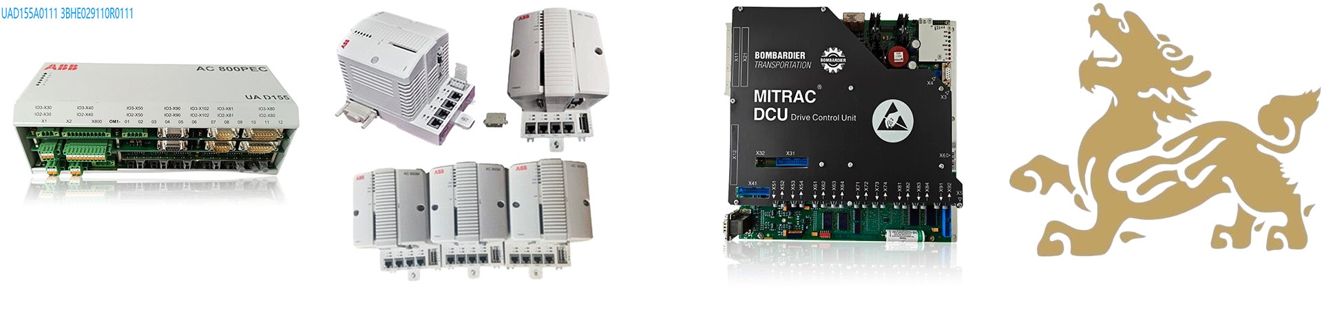
MVB Class 4 (EMD Interface): Supports 1.5Mbps speed, used for real-time communication with train networks (such as traction converters and braking systems). Requires a dedicated MVB network card or converter to connect to a computer.
RS485 Maintenance Port: Used for device debugging and diagnostics. Requires an RS485 to USB converter (such as an FT232 module) to connect to a computer’s serial port or USB interface.
Ethernet (Optional): Some models may support Ethernet interfaces (such as LAN1/LAN2). Requires an RJ45 network cable to connect to a computer or switch.
RS485 Maintenance Port
Interface Type: 1 × RS485 (maintenance port), used for device debugging, log reading, and firmware updates.
Connection Steps:
Use an RS485 to USB converter (such as an FTDI chip solution) to connect the device’s RS485 port to the computer’s USB interface.
Install the corresponding serial port driver on the computer (e.g., Windows system automatically recognizes or manually installs the FTDI driver).
Configure serial port parameters: Typically 9600 baud rate, 8 data bits, 1 stop bit, no parity (refer to the device manual for confirmation).
Access the device via dedicated software (such as the Bombardier diagnostic tool) to perform configuration, log export, or firmware upgrades.
MVB Class 4 Interface
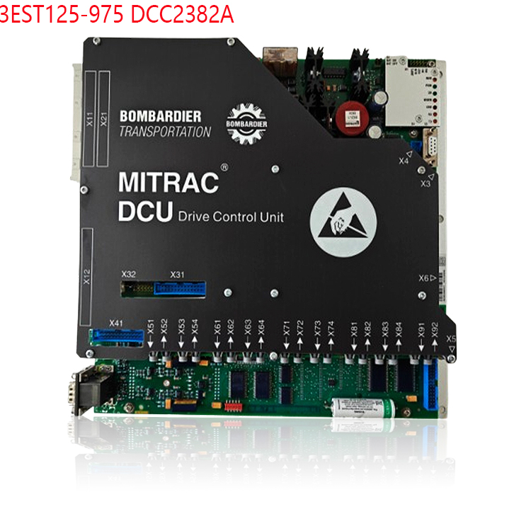
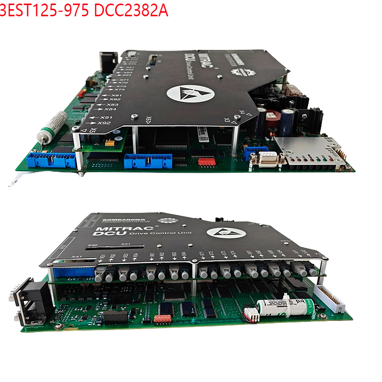
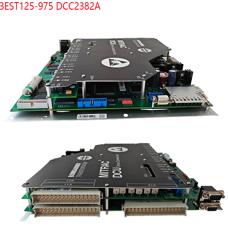
Interface Type: 2 × MVB (Multifunction Vehicle Bus) EMD interfaces, used for train-level real-time data communication (such as traction/braking control).
Connectivity Limitations: Requires a dedicated MVB network card (such as an EMD protocol converter) and a train network simulation environment. It is usually not directly connected to a regular computer and is mostly used on train test benches or dedicated test systems (such as the MTT-1500 test bench).
Power Requirements:
Input voltage 24VDC (range 16-36VDC). Ensure the power supply is stable and meets the device’s lightning protection/interference immunity standards.
Software Configuration and Tools
Official Tools:
Bombardier Configuration Software: Such as MITRAC Control System or dedicated diagnostic tools. These require connection to the device via RS485 or Ethernet interface and support parameter configuration, firmware updates, and fault diagnosis.
ABB Tool Compatibility: If the device integrates ABB components (such as some control modules), programming and monitoring can be performed using ABB RobotStudio, Control Builder M, or Servo Composer. IP address (e.g., 192.168.125.1) and communication protocol (e.g., Modbus TCP, PROFINET) need to be configured.
Third-Party Tools:
Serial Port Debugging Tools: Such as Putty, SecureCRT. These allow setting the baud rate (9600-115200), data bits, stop bits, and parity bits via RS485 interface.
Network Configuration Tools: Such as Wireshark packet capture analysis, or using TCP/IP testing tools to verify Ethernet connectivity.
Software and Tool Requirements
Dedicated Diagnostic Software: Bombardier may provide accompanying configuration tools or diagnostic platforms (such as MITRAC Control), which must interact with the device via RS485 or MVB interfaces, supporting parameter configuration, fault diagnosis, and real-time data monitoring.
Protocol Support: Ensure the software is compatible with the MVB time-triggered protocol and RS485 serial communication protocol. Custom communication scripts may be required in some scenarios.
Security Authentication: The device supports SIL 2 security level. Before operation, confirm that the computer software has the corresponding security authentication to avoid unauthorized access leading to system abnormalities.
Connection Steps
Hardware Connection:
Use an RS485 to USB converter to connect the device’s maintenance port to the computer’s USB port, or connect the device’s network port to the computer’s network card via an Ethernet cable.
Ensure a stable power input (24VDC) and check grounding and surge protection measures.
Software Configuration:
Serial Port Settings: Configure the serial port parameters on the computer (e.g., baud rate 9600, 8 data bits, no parity, 1 stop bit), open the serial port debugging tool, and connect to the device.
Network Configuration: If using Ethernet, assign an IP address to the computer on the same network segment as the device (e.g., 192.168.125.5), and test connectivity using the Ping command.
Protocol Adaptation: Configure the corresponding protocol parameters and register mappings in the software according to the protocols supported by the device (e.g., MVB, Modbus, PROFINET).
Diagnosis and Debugging:
Use official tools to read the device status, fault logs, and operating parameters.
Monitor the device status using LED indicators (e.g., POWER, STATUS lights), and analyze problems in conjunction with serial port output or network data packets.
Precautions:
Safety Standards: The device complies with SIL 2 safety level. During connection, adhere to standards such as IEC 61508 and EN 50126/8/9 to ensure safe operation.
Compatibility Verification: Confirm the compatibility between the computer operating system (e.g., Windows 10/11) and the driver to avoid connection failures due to driver issues.
Anti-interference Measures: In industrial environments, shielded cables must be used and the device kept away from strong electromagnetic interference sources to ensure communication stability.
Power Supply and Protection: The device requires 24VDC power (range 16-36VDC). Ensure stable power supply during connection. IP67 protection rating requires waterproof and dustproof interfaces; avoid unauthorized disassembly.
Environmental Adaptability: The device supports a wide operating temperature range of -40°C to +85°C. The computer must ensure stable operation under the same environment (e.g., industrial-grade computer or temperature-controlled environment).
Access Control: Device connection and configuration must be performed by qualified personnel to prevent unauthorized access that could lead to system failure.
Typical Application Scenarios
Rail Vehicle Commissioning: Connect to the train network via the MVB interface to monitor the traction/braking system status in real time and adjust control parameters.
Industrial Automation: In factory environments, connect to a PLC or SCADA system via Ethernet or serial port for remote monitoring and data acquisition.
Fault Diagnosis: Use the RS485 interface to connect a diagnostic tool, read the device fault codes and operating logs, and quickly locate the problem.
Summary: Connecting the DCC2223A 3EST125-977 requires a combination of hardware interfaces (MVB/RS485/Ethernet) and software tools (official configuration software, serial port debugging tools). Communication with the computer is achieved through physical connections, parameter configuration, and protocol adaptation.
Related product recommendations:
S-093H 3BHB030478R0009
S-093M 3BHB009885R0013
S-093R 3BHB009885R5311
S-097H 3BHB009885R0052
S-093M 3BHB009885R0063
ABB S-093H 3BHB030478R0309
ABB S-093S 3BHB030475R0009
S-093S 3BHB030475R0009
S-073N 3BHB009884R5211
S-073N 3BHB009884R0021 35SHY3545L0014
S-053M 3BHB012897R0003
S-073N 3BHB009884R0021 35SHY3545L0014
S-073N ABB 3BHB009884R0021
S-097H 3BHB009885R0052
S-093H 3BHB030478R0309
More……