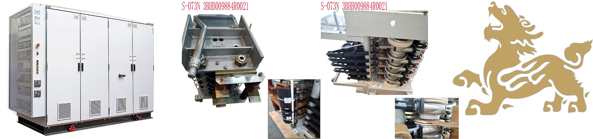
ABB Excitation Controller Module 3BHE017628R0002 PPD115A02 SG579989013 Software Installation Guide
I. Compatible Software and Versions
Core Software:
Control Builder M: A dedicated programming tool for ABB AC800PEC series controllers, supporting hardware configuration and IEC61131-3 standard programming (such as ladder diagrams and structured text). Compiled programs can be downloaded to the controller for simulation verification.
System 800xA Platform: ABB’s integrated automation platform, supporting secondary development, system configuration, network communication, and database management, compatible with the AC800PEC controller module.
.jpg)
Version Requirements:
Requires matching controller firmware version (e.g., AC800PEC series firmware). It is recommended to use the latest version officially recommended by ABB (e.g., System 800xA V6.0 and above).
II. Installation Steps
System Environment Preparation:
Operating System: Windows 7/8/10 (64-bit), antivirus software and firewall must be disabled.
Hardware Requirements: Intel Core i5 or higher processor, 8GB or more of RAM, 20GB or more of hard disk space, and a graphics card supporting OpenGL 2.1.
Network Configuration: Ethernet connection, supporting TCP/IP protocol, the controller IP address must be on the same network segment as the engineering station (e.g., 192.168.1.x).
Software Installation Process:
Download Installation Packages: Obtain the System 800xA and Control Builder M installation packages from the ABB official website or authorized channels.
Extraction and Installation:
Extract the installation packages to a directory without Chinese characters in the path (e.g., C:\ABB_Install).
Run setup.exe, select “Simplified Chinese,” accept the license agreement, and select “Full Installation” or custom components (e.g., development tools, communication modules).
Keep the installation path as default or modify it to a path without Chinese characters to avoid installation errors.
After installation, start System 800xA and perform initial configuration (such as database connection and network settings).
Controller Configuration:
Hardware Connection: Connect the controller to the engineering station via Ethernet or serial port (such as RS232) to ensure normal communication.
IP Address Settings: Configure the controller’s IP address, subnet mask, and gateway (such as 192.168.1.10/255.255.255.0) in System 800xA.
Module Configuration: Add the AC800PEC controller module in Control Builder M, and configure the I/O modules (such as S800 series) and communication protocols (such as Modbus TCP, PROFINET).
2. Hardware Connection and Network Configuration
Physical Connection:
Use an RJ45 Ethernet cable to connect the controller’s CN1/CN2 ports to the engineering station PC, or connect the COM4 (RS232) port via a TK212 serial cable.
Ensure the controller and PC are on the same subnet (e.g., 192.168.1.0/24), and set static IP addresses (e.g., controller IP: 192.168.1.100, PC IP: 192.168.1.5).
IP Address Configuration:
Launch the IPConfig tool (path: ABB Start Menu > Engineering > Utilities), select the controller port (e.g., CN1), enter the target IP address, and save.
Verify Connectivity: Ping the controller IP address from the PC to ensure no packet loss.
3. Hardware Configuration and Program Development
Hardware Configuration:
Create a new project in Control Builder M, adding the controller model (e.g., AC800M) and I/O modules (e.g., S800 series).
Configure Module Parameters: Set the I/O address (e.g., %IW100 for analog input), communication protocol (e.g., Modbus TCP, PROFINET), and redundancy mode (e.g., Hot Standby).
Programming and Download:
Write the control logic (e.g., PID algorithm, interlocking logic), compile it, and then push it to the controller via the “Download” function.
Debugging Tools: Use the online monitoring function to view variable values, or verify the program logic through simulation mode.
4. System Integration and Verification
HMI and Alarm Management:
Design the operation interface using the 800xA Graphics Editor, bind variables (e.g., PV_T101), and set alarm thresholds (e.g., high temperature 90℃).
Configure the alarm manager and historical database to record key events and trend data.
Redundancy and Communication Testing:
Manually switch between primary and backup controllers to verify the redundancy switching time (≤500ms).
Test Profibus/Modbus communication to ensure correct data mapping for slave devices (e.g., frequency converters).
Program Development and Download:
Write the control logic (e.g., PID algorithm), compile it, and then download it to the controller via Syst em 800xA.
Use simulation to verify program correctness, ensuring the control cycle (e.g., 100ms) and response time meet requirements.
III. Key Considerations
Compatibility Verification: Before installation, confirm software version compatibility with controller firmware to avoid version conflicts leading to functional abnormalities.
Path Standardization: Installation paths and project file paths must not contain Chinese characters to prevent encoding errors.
Access Control: Installation and configuration require administrator privileges to ensure system security.
Firmware Updates: Regularly update controller firmware using ABB tools to fix vulnerabilities and improve performance.
Troubleshooting: If installation or operation is abnormal, check log files (e.g., installation logs, system events) and contact ABB technical support for official solutions.
IV. Maintenance and Expansion
Module Expansion: Connect more I/O modules (e.g., S800 series) via fiber optic links to expand system functionality.
Firmware Upgrade: Update controller firmware using ABB tools (e.g., Firmware Update Tool) to ensure compatibility and security.
Regular Maintenance: Clean module dust, check connector and cable integrity, and ensure good heat dissipation.
In summary, by installing the System 800xA platform and Control Builder M software, and combining the correct hardware configuration and program development, the ABB excitation controller module can achieve efficient operation and precise control.
Recommended models:
PFVK 135 3BSE007135R1
PFRL101C 2.0KN 3BSE002964R002
PFSA103B 3BSE002487R1
PFXA401S 3BSE024388R2
PPD103801 3BHE020455R0001
PPD513AOC-100440 3BHE039724R0C3D
PPD517A3011 3BHE041576R3011
PPD517 3BHE041576R3011
GFD563A102 3BHE046836R0102
GFD233A101 3BHE022294R0101
GFD563A101 3BHE046836R0101
GFD563A102 3BHE046836R0102
GF D563 3BHE046836R010
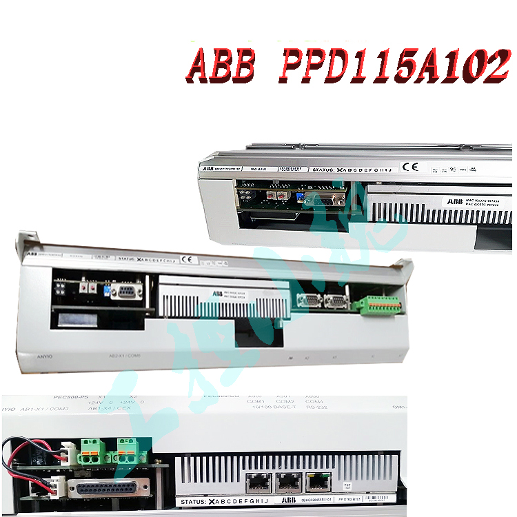
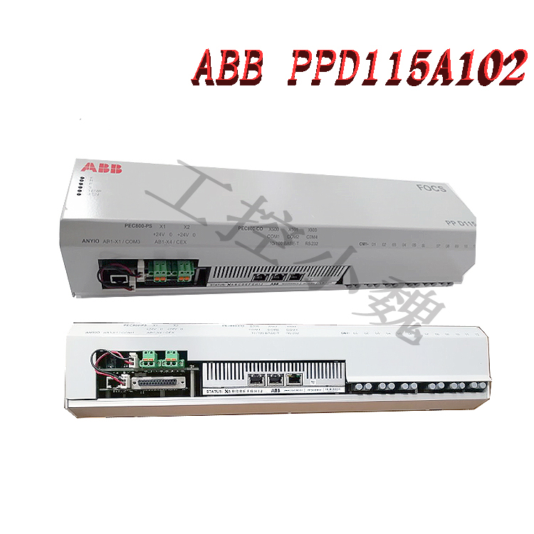
PPD115A102
3BHE017628R0102 PPD115A102
PPD115A102 3BHE017628R0102
PPD115A102
PPD115A102 controller
SYN5201A-Z V277 3BHB006714R0277
3BHB006714R0217
SYN5201A-Z V217 3BHB006714R0217
SYN5200a-Z 3BHB006713R0217
PPD539A102 A 800PEC 3BHE039770R0102
PPD539A102 A800PEC
PPD513A24–110110
PPD513A24–110110 3BHE039724R2441
PPD513 A24-110110
PPD513 A24-110110 3BHE039724R244
3BHB006713R0217
PPD512A10-454000 3BHE040375R103
PPD513A24–110110 3BHE039724R2441
3BHE057901R0101 PCD235
PCD235C101 3BHE057901R0101
PCD235C101 PCD235
GFD563A101 3BHE046836R0101
ABB GFD563A102 3BHE046836R0102
ABB GF D563 3BHE046836R010
PCD235C101 3BHE057901R0101
more……
I always look forward to your posts. Keep it coming!
I like how you kept it informative without being too technical.
I appreciate the real-life examples you added. They made it relatable.
I wasn’t sure what to expect at first, but this turned out to be surprisingly useful. Thanks for taking the time to put this together.
Keep writing! Your content is always so helpful.
Thanks for making this so reader-friendly.
This post cleared up so many questions for me.
Thank you for covering this so thoroughly. It helped me a lot.
Very relevant and timely content. Appreciate you sharing this.