
Description
Many products are not yet listed. Please contact us for more information.
If the product model differs from the displayed image, the model number shall prevail. Please contact us for specific product images, and we will arrange to take photos in our warehouse for confirmation.
We have 76 shared warehouses worldwide, so it may sometimes take several hours to accurately return the information to you. We appreciate your understanding. Of course, we will respond to your inquiries as soon as possible.
Model: LG1093AA36
Brand: Honeywell (now handled by ONTIC for this product line)
Type: Ultraviolet (UV) Flame Sensor
Cable Specification: 61 feet (18.6m) Teflon-shielded cable
Explosion-proof Rating: CENELEC IIA, ATEX II 2G Ex db IIA T3 Gb
II. Core Working Principle
Utilizes a Geiger-Miller GM UV phototube, specifically designed to detect the 180–260nm deep ultraviolet band emitted by hydrocarbon flames:
The probe incorporates a Geiger UV phototube, receiving only the short-wave ultraviolet light emitted by the flame; in the absence of a flame, there is no ultraviolet signal, and the amplifier outputs a flameout fault signal, triggering fuel cut-off and alarm interlock to prevent gas leaks and deflagration.
Solar blindness characteristic: Unaffected by sunlight or high-temperature blackbody infrared radiation, exhibiting extremely strong anti-interference capabilities;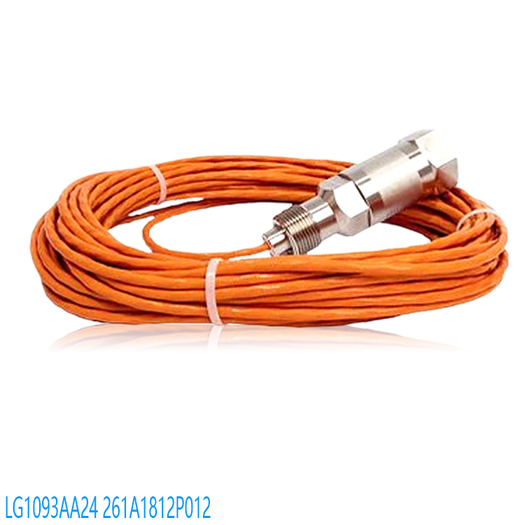
Only identifies ultraviolet signals from gas/oil flames; furnace high temperatures and lights will not trigger false alarms;
When used with matching amplifiers (EG1033AA01/AC01/AD01), outputs a flame presence/absence switch signal for gas turbine flameout protection interlocking.
III. Key Technical Parameters
Detection Wavelength: 1800–2600Å (180–260nm) Ultraviolet Light
Installation Interface: 3/4-inch internal NPT thread, compatible with gas turbine observation port
Cable Outlet: 1-inch external conduit thread, orange Teflon double-shielded cable
Operating Temperature: -40℃ ~ +177℃ (-40℉ ~ 350℉)
Lifespan Indicators: MTBF 10,000 hours, shelf life 2 years
Response Speed: Flame detection ≤0.1s; Flameout signal interruption ≤0.2s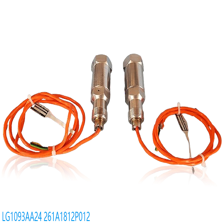
Pressure Resistance Window: 150psig @ 204℃
Transmission Distance: Sensor to amplifier up to 300 meters (1000ft)
IV. Explosion-Proof and Compliance Certifications
FM Explosion-Proof Certification: Class I Div 1/2, Hazardous Gas Groups B/C/D
ATEX 2014/34/EU, IECEx Global Explosion-Proof Certification
CE, EMC Electromagnetic Compatibility Certification, applicable to explosion-proof factories in Europe
Differentiation of Models in the Same Series (Cable Length Differences)
Model | Cable Length | ATEX Explosion-Proof Rating
LG1093AA24186 inch (4.7m) IIC
LG1093AA26726 inch (18.6m) IIC
LG1093AA36726 inch (61ft/18.6m) IIA
LG1093AA4416ft (4.9m) IIC
LG1093AA4542ft (12.8m) IIC
LG1093AA4661ft (18.6m) IIC
Typical Application Scenarios
GE All Gas Turbines (Mark V/VI Control System with Standard Flame Probe)
Large Industrial Natural Gas Turbines / Heavy oil boilers, heating furnaces, incinerators
Power plants, refineries, explosion-proof combustion systems, flameout interlock protection
Requires long-distance wiring (18.6 meters), low explosion-proof rating IIA, gas-fired operation
I. Installation Prerequisites & Safety Requirements
Explosion-proof Safety
This model, ATEX II 2G Ex db IIA T3, FM Class I Div1, is explosion-proof. Explosion-proof tools must be used throughout the process. Operations in the furnace and gas turbine areas must be completed with the machine shut down, pressure released, fuel cut off, and the machine locked and tagged.
Mandatory Temperature Cooling Requirements
The probe body can withstand a maximum ambient temperature of 177℃, but if the temperature on the furnace side of the mounting base exceeds 80℃, a water-cooled/air-cooled mounting sleeve is required:
Air-cooled: Clean, dry instrument air, pressure 0.02~0.05MPa, continuously blowing to prevent oil contamination and high-temperature radiation from the lens;
Water-cooled base: Circulating cooling water ≤40℃ outlet, preventing high-temperature conduction that could burn out the UV phototube.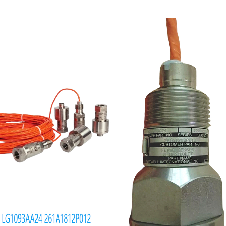
Cable Foundation
The LG1093AA36 comes with an 18.6m Teflon-armored shielded dual-core cable, which must not be cut or extended; the cable end is threaded into the EG1033 amplifier’s explosion-proof junction box via a 1-inch external NPT conduit.
II. Installation Location Selection (Core, directly determining detection reliability)
Unobstructed Field of View
The probe’s central axis must directly view the main combustion zone of the flame, without obstruction from pipes, refractory materials, or nozzles; ordinary glass will block UV light, so the addition of ordinary observation glass is prohibited.
Angle Standards
The probe lens should be tilted downwards at 10°~30° to avoid condensation and oil accumulation on the lens; the angle between the lens axis and the flame center should be ≤15° to prevent significant signal attenuation.
Distance Specifications
The optimal distance between the standard observation port and the flame is 0.8~4m; distances exceeding 4m may result in weak flame signals and false alarms due to flameout.
Interference Avoidance
Avoid welding, strong ultraviolet arc light, and direct sunlight (this model is sunblind, but strong instantaneous ultraviolet light can still cause interference);
Keep away from frequency converters and high-power motors (armored shielded cables must be reliably grounded at one end to suppress EMI);
Each burner should be equipped with its own independent probe; sharing probes to monitor multiple burners is prohibited.
Vibration Control
Reinforce the mounting bracket and add anti-vibration pads; high-vibration parts of the gas turbine must use rigid flange bases to prevent angle shift.
III. Mechanical Installation Steps (3/4″ Inner NPT Standard Thread)
Step 1: Base/Sleeve Pre-installation
Weld a 3/4″ outer NPT mounting sleeve to the boiler/gas turbine observation hole. The sleeve’s inner diameter should be ≥φ18 to ensure unobstructed light path;
Install water-cooled/air-cooled sleeves for high-temperature operation, connect the cooling medium pipeline, and pressure test for leaks;
Add a universal adjustment bracket to the outside of the sleeve for easy fine-tuning of the probe’s viewing angle later. Step 2: Probe Thread Assembly
Wrap high-temperature explosion-proof PTFE tape around the inner 3/4″ NPT thread of the probe tip (metal thread seal, ordinary tape is prohibited);
Manually screw in the sleeve, and finally tighten with an explosion-proof wrench. Do not force it (to prevent the internal UV tube from shattering);
Rotate the universal bracket, visually align it with the center of the flame, and tighten all fixing bolts of the bracket.
Step 3: Cable Wiring Protection
Route the self-armored cable naturally. The minimum bending radius should be ≥ 10 times the cable’s outer diameter. Do not bend or squeeze it.
The 1-inch outer NPT cable outlet should be protected with an explosion-proof flexible conduit. Lay it separately in the cable tray, not in the same slot as the power cable;
Avoid contact between the cable and high-temperature conduit walls throughout the entire process (conduits >100℃ require a heat insulation sleeve).
IV. Electrical Wiring (Matching EG1033AA01/AC01) Flame Amplifier)
Power-off Operation: The amplifier cabinet must be completely powered off before opening the cover. The explosion-proof cavity sealing gasket must not be lost or damaged.
Cable Shielding and Grounding Rules (Critical Anti-interference)
The armored metal shield is grounded only at a single point on the amplifier end; the shielding layer on the probe end is suspended and not grounded.
The grounding wire is connected to the dedicated explosion-proof grounding busbar of the control cabinet, with a grounding resistance <4Ω.
Terminal Wiring Definitions (Two-core cable, no polarity, neither wire is positive or negative)
The two shielded core wires of the probe are directly connected to the amplifier’s **SIG+, SIG-** signal terminals.
Amplifier Power Supply: 24VDC/115VAC Connect the power supply terminals according to the model number;
Connect the amplifier relay dry contact output to the furnace safety interlock (flameout shutdown circuit).
Explosion-proof seal restoration
Fill the cable conduit joints with explosion-proof sealant, tighten all bolts of the amplifier explosion-proof box, ensuring the explosion-proof cavity is completely sealed.
V. Post-installation commissioning and testing
Cold insulation test
Use a multimeter to check that the cable has no short circuit, and the insulation to ground is ≥20MΩ; there is no continuity between the shielding layer and the core wire.
Pre-run with ventilation and cooling
First turn on water cooling/air cooling, and wait for the probe base to cool down to below 60℃ before powering on.
Ignition flame verification
Normal ignition: The amplifier’s “flame present” indicator light remains on, and the relay engages;
Flameout: 0.2s Internal relay disconnects, triggering safety shutdown interlock;
Weak signal: Fine-tune the universal bracket to reduce the angle between the lens and the flame.
Interference Test
Start and stop the fan and frequency converter, observe the amplifier for false flame signals; if a false alarm occurs, check the shielding grounding and cable separation.
VI. Prohibited Practices & Common Fault Avoidance
❌ Do not cut or lengthen the original armored cable, as this will increase distributed capacitance and cause false detections;
❌ Direct contact between the probe and temperatures above 80℃ without cooling can easily burn out the UV capping tube;
❌ Double-ended grounded shielded cables will introduce circulating current, causing signal jitter;
❌ Lens mounted horizontally or upwards will accumulate oil and condensation, obstructing the light path;
❌ Ordinary transparent glass between the probe and the flame will prevent UV penetration;
❌ The power cable and probe cable are laid in the same conduit, causing frequent false alarms due to electromagnetic interference.
VII. Key Points for Daily Post-Installation Maintenance
Weekly check water/air cooling flow and ensure there are no blockages;
Monthly disassemble the probe and clean the viewing window lens (wipe with a soft cloth and anhydrous alcohol; do not scratch with hard objects);
Quarterly tighten the bracket and explosion-proof threads to prevent vibration from loosening and shifting the viewing angle.
Recommended related products:
LG1093AC01 | Flame Detector | HONEYWELL | LG1093AC01
LG1093AA46 | Flame Detector | HONEYWELL | LG1093AA46
LG1093AA45 | Flame Detector | HONEYWELL | LG1093AA45
LG1093AA36 | Flame Detector | HONEYWELL | LG1093AA36
LG1093AA25 | Flame Detector | HONEYWELL | LG1093AA25
LG1093AA35 | Flame Detector | HONEYWELL | LG1093AA35
CC-PAOH01
CC-IP0101
CC-IP0101 51410056-175
CC-MCAR02
CC-PAIH01 51405038-175
CC-PAIH01
CC-PAIH02
CC-PAIH51 51410069-275
CC-PAIH51
CC-PAIM01 51405045-175
TC-PPD011
TC-ODK161
TC-FPCXX2
TC-CCR014
05701-A-0502
05701-A-0301
05701-A-0451
05701-A-0327
05701-A-0283
05701-A-301ISS
05701-A-0288
05701-A-0294
05704-A-0123
05704-A-0146
More……

admin –
The LG1093AA36 Honeywell industrial gas turbine-specific UV flame detector, paired with the matching EG1033 flame amplifier, forms a complete flame monitoring system. It is a standard flame detection element for GE series gas turbines, used for real-time monitoring of the presence of flames in the combustion chamber, and is a core component for combustion safety protection.
Detection Principle: Geiger-Müller phototube, capturing the exclusive ultraviolet band of hydrocarbon flames (185–265nm), solar blind, unaffected by high-temperature blackbody infrared radiation from the furnace or sunlight, eliminating false alarms.
Core Functions:
1. Real-time UV detection of flame presence (core function)
Continuously collects ultraviolet signals generated by gas/oil combustion, converts them into a weak electrical signal, and transmits it to the EG1033 amplifier;
Flame detection response: typical 0.1s, maximum ≤1s; flameout/extinguishment response ≤0.2s, extremely fast identification of flameout and extinguishment faults;
Distinguishes between real flames and high-temperature reflections from the furnace, natural light, and equipment thermal radiation, avoiding false alarms of “flame presence”.
2. Built-in Current Limiting Protection Hardware
The probe integrates a 511Ω/2W wire-wound current-limiting resistor. The amplifier outputs 350VDC high voltage to supply the probe. The built-in resistor prevents short circuits and leakage from damaging the phototube, extending the probe’s lifespan.
3. Explosion-Proof Industrial Installation and Field Adaptability
The probe body has an explosion-proof structure: Class I Div1/2, ATEX Ex db IIC T3 explosion-proof certification, suitable for gas turbines and oil and gas explosion-proof areas; Mounting threads: 3/4 NPT internal thread, for connecting to the observation lens sleeve; 1-inch external conduit thread for connecting armored shielded cable; Wide temperature tolerance and vibration resistance, suitable for high-temperature gas turbine housing installation environments.
4. Stable Long-Distance Signal Transmission
Supports armored cable wiring up to 300 meters (1000ft) between the probe and amplifier, ensuring no attenuation of weak ultraviolet signals over long distances, suitable for large gas turbine generator room layouts.
5. Safety Interlock Signal Output via Amplifier
The probe only collects ultraviolet light. The signal is sent to the EG1033 amplifier, which outputs two types of safety signals:
Switching relay contacts: for Woodward/GE turbine controllers and combustion management systems (BMS);
Open collector transistor signals: uploaded to the DCS/HMI, displaying normal flame/flameout alarm;
Upon receiving a no-flame signal, the unit logic immediately triggers: fuel cut-off, shutdown, and purge protection to prevent deflagration and furnace explosions.
6. Long-Term Stable Continuous Operation
MTBF (Mean Time Between Failures) is 10,000 hours, ensuring long-term continuous operation of the industrial generator set;
2-year shelf-storage life;
EMC certification for electromagnetic interference resistance, protecting against interference from inverters and high-voltage motors, ensuring stable and drift-free signals.
https://www.weikunfadacai1.com/product/lg1093aa36-flame-detector-honeywell-lg1093aa36/