
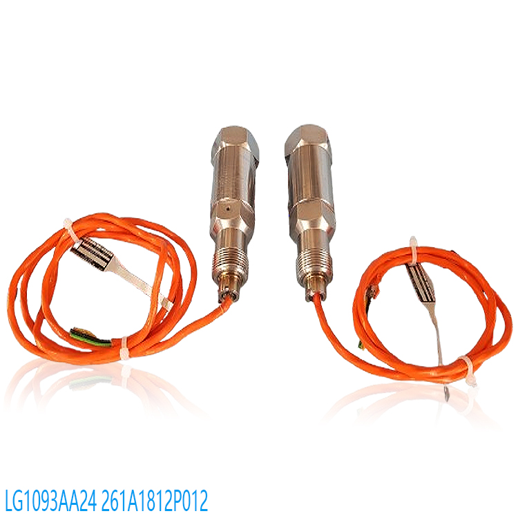
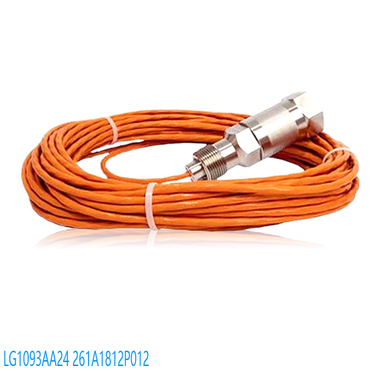
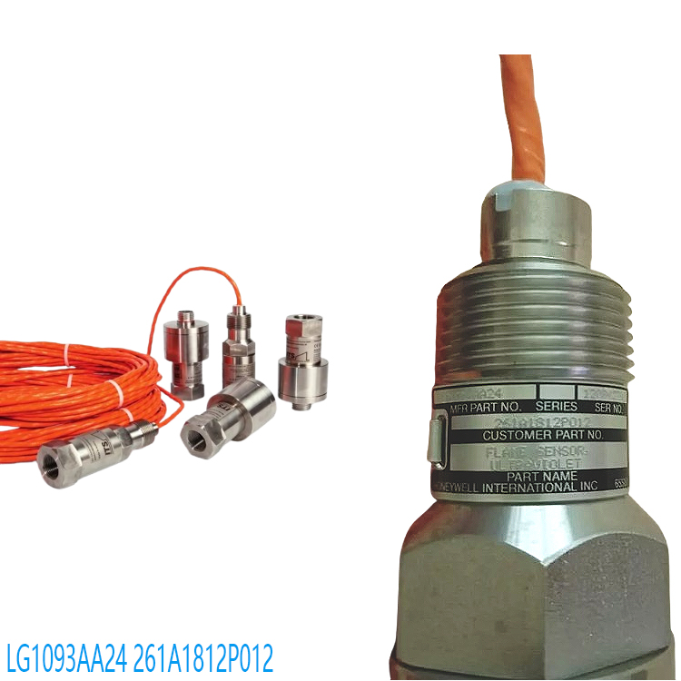
HONEYWELL LG1093AC01 Flame Sensor Usage Precautions
I. Installation Specifications
Location Selection
Location and Direction
The sensor must be directly facing the core flame area (e.g., gas turbine combustion chamber, boiler furnace center), avoiding furnace wall reflections, obstructions, and flue gas obstruction paths. It is recommended to install at a 45° angle or vertically downwards, avoiding direct contact with reflective objects (e.g., metal, glass). The detection distance needs to be calibrated by rotating the sensor potentiometer; generally, the response time is ≤0.2 seconds when a flame is present.
Environmental Protection
The installation location must be far away from high-temperature radiation areas (e.g., furnace door gaps, hot air ducts), strong electromagnetic interference sources (inverters, motors), and flickering light sources (welding, strong lighting). The operating temperature range is -40℃ to +85℃; this range must be avoided. The IP67 protection rating requires dust and water resistance during installation; however, long-term exposure to high humidity or corrosive gas environments requires a protective cover.
Anti-interference design: Keep away from electromagnetic interference sources (such as frequency converters, motors), strong light sources (such as welding, lighting), and vibration sources. Use shielded cables and ensure proper grounding. The transmission distance should not exceed 330 meters.
Electrical Connection
Wiring Standard: Connect the red/black wires to the positive/negative terminals (24V or 28VDC) respectively. Connect the signal wire (yellow) to the designated port of the equipment (such as the DI port). Reverse connection is strictly prohibited. Avoid voltage fluctuations (must be stable at 20-35VDC or 115VAC).
Line Testing: Use a multimeter to check the power supply voltage, line continuity, and signal cable shielding effectiveness to avoid open circuits, short circuits, or poor contact.
II. Maintenance and Calibration
Regular Cleaning
Lens Maintenance: Clean the sensor window weekly with anhydrous alcohol and a soft brush. Increase the frequency in high-dust environments to prevent oil and dust from affecting sensitivity.
Heat Dissipation Hole Cleaning: Regularly clean the sensor’s heat dissipation holes to prevent high temperatures from causing internal component failure.
Performance Testing
Response Verification: Test at close range using a lighter or flame simulator. A normal response time is approximately 0.2 seconds. If there is no response, check the power supply, wiring, or the sensor itself.
Sensitivity Calibration: Adjust the trigger threshold by rotating the potentiometer (clockwise to increase sensitivity, counter-clockwise to decrease) to avoid false triggering by ambient light or minor fluctuations.
Lifespan Management
The sensor’s lifespan is typically 2-5 years. Regularly check for signs of aging (such as cracked casing, burnt circuit board components, bulging capacitors). Replace immediately if the sensor is past its lifespan or damaged.
III. Safety and Emergency Response
Operational Safety
Do not disassemble the sensor yourself, as this will void the warranty. Maintenance must be performed by qualified personnel, complying with national fire safety regulations and manufacturer requirements.
Avoid placing the sensor directly on reflective objects (such as glass or metal) to prevent reflected light from interfering with detection.
Troubleshooting
Unable to Detect Flame
Check the power supply and wiring (confirm 24V DC power and continuity), installation location (whether it is directly facing the flame), and environmental interference (high temperature, electromagnetic interference, light interference). If there is still no response after cleaning, the sensor or amplifier may need to be replaced.
False Alarm/Missed Detection
Adjust the sensitivity threshold (rotary potentiometer) to reduce the impact of ambient light and infrared interference. Check the controller threshold settings and response delay to avoid false triggering due to flame fluctuations or signal noise.
Emergency Situation: In case of flame extinguishing or abnormality, the sensor should immediately trigger an alarm and cut off the fuel supply, activating emergency plans (such as evacuation and fire extinguishing).
Complete No Response
Check the power supply, signal lines, and amplifier power supply (whether 220VAC is normal). Confirm that the sensor is not physically damaged (burned, cracked). If self-troubleshooting is ineffective, contact the manufacturer’s after-sales service to avoid voiding the warranty due to self-disassembly.
System Compatibility and Safety
Compatibility with PLC, DCS, and other control systems is required, ensuring signal interface matching (e.g., 4-20mA, switch output). The system configuration needs to adjust threshold and delay parameters to avoid detection failure due to improper parameter settings.
Operators need to receive professional training and master basic troubleshooting skills (such as multimeter use and circuit testing). Disassembling the sensor is prohibited for non-professionals to avoid damaging internal components or voiding the warranty.
IV. Environment and Compatibility
Special Environment Adaptation
High Dust/High Humidity: Increase cleaning frequency and use a dustproof and waterproof design (IP67 rating) to prevent dust blockage or moisture short circuits.
Chemical Combustion: Not suitable for detecting the combustion of phosphorus, sodium, magnesium, and other chemicals; a dedicated sensor must be used.
V. Regulations and Records
Compliance Requirements: Complies with IEC 60947-5-1, CE, UL, CSA, and other standards. Installation must comply with national and local fire safety regulations.
Maintenance Records: Regularly record cleaning, testing, calibration, and maintenance information, and maintain records for future reference.
By strictly following the above precautions, the HONEYWELL LG1093AC01 flame sensor can be ensured to operate efficiently and safely in industrial environments, guaranteeing the safety and efficiency of the combustion process. For complex issues, it is recommended to contact Honeywell technical support or a professional engineer for diagnosis.
Recommended related products:
CC-PAOH01
CC-IP0101
CC-IP0101 51410056-175
CC-MCAR02
CC-PAIH01 51405038-175
CC-PAIH01
CC-PAIH02
CC-PAIH51 51410069-275
CC-PAIH51
CC-PAIM01 51405045-175
TC-PPD011
TC-ODK161
TC-FPCXX2
TC-CCR014
05701-A-0502
05701-A-0301
05701-A-0451
05701-A-0327
05701-A-0283
05701-A-301ISS
05701-A-0288
05701-A-0294
05704-A-0123
05704-A-0146
CC-PAOH01
CC-IP0101
CC-IP0101 51410056-175
CC-MCAR02
CC-PAIH01 51405038-175
CC-PAIH01
CC-PAIH02
CC-PAIH51 51410069-275
CC-PAIH51
CC-PAIM01 51405045-175
TC-PPD011
TC-ODK161
TC-FPCXX2
TC-CCR014
More……