

Description
Many products have not been listed yet. For more products, please contact us
If the product model is inconsistent with the displayed image, the model shall prevail. Please contact us for specific product images, and we will arrange for photos to be taken and confirmed in the warehouse
We have 16 shared warehouses worldwide, so sometimes it may take several hours to accurately return to you. We apologize for any inconvenience caused. Of course, we will respond to your concerns as soon as possible.
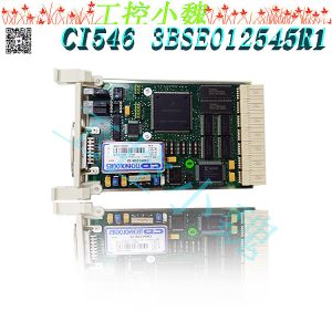
GFD233A101 3BHE022294R0101 Other names:
GFD233A101 3BHE022294R0101 control unit
Output unit module GFD233A101 3BHE022294R0101
Analog unit GFD233A101 3BHE022294R0101
Function Introduction
GFD233A101 3BHE022294R0101 excitation controller is an excitation regulator for self parallel excitation static rectification excitation systems, evolving from semiconductor discrete components to integrated solid components and from analog to digital. Domestic devices can be divided into three categories: semiconductor analog excitation regulators, microcomputer (including programmable controllers) digital excitation regulators, and hybrid microcomputer (including programmable controllers) analog excitation regulators. Domestic semiconductor excitation regulators have a record of export since the early 1970s. The development of microcomputer excitation regulators began in the late 1970s..jpg)
The GFD233A101 3BHE022294R0101 controller has the following characteristics:
Error control: The device controller also manages error detection of data transmitted by I/O devices. If an error is found during transmission, the error detection code is usually set and reported to the CPU, so the CPU invalidates the data transmitted this time and performs a new transmission. This ensures the accuracy of data input..jpg)
Data exchange: This refers to the exchange of data between CPUs and controllers, as well as between controllers and devices. For the former, data is written to or read from the controller in parallel by the CPU through the data bus; For the latter, it is the device that inputs data to the controller or transmits it from the controller to the device. Therefore, data registers must be set in the controller.
Receive and recognize commands: The CPU can send various different commands to the controller, and the device controller should be able to receive and recognize these commands.
All products on this website are special products, and market prices have been fluctuating,
The specific customer service quotation shall prevail, as the product is a new one and the traps are not real,
Please confirm the model, product, price, and other detailed information with customer service before placing an order. The website has been used,
New for sale, please contact the website https://www.weikunfadacai1.com/ Customer service communication.
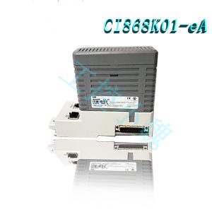
Recommended modules with the same function:
GFD563A101
GFD563A101 3BHE046836R0101
GFD563A102
GFD563A102 | 3BHE046836R0102
GFD212A 3BHE020357P201
GFD212A 3BHE020356R0101
GFD233A 3BHE022294R0103
GFD233A
GFD233A103
KUC321AE HIEE300698R1
3BHB004661R0101
PPD512 A10-15000 3BHE040375R1023
3BHE017628R0002 PPD115A02 SG579989013
UAD149A1501 3BHE014135R1501
UAD142A01 3BHE012551R0001
PPD513AOC-100440 3BHE039724R0C3D
PPD517A3011 3BHE041576R3011
PPD517 3BHE041576R3011
PPD512A10-454000 3BHE040375R103E
3BHE057901R0101 PCD235
PCD235C101 3BHE057901R0101
GFD563A102 3BHE046836R0102
GFD563A101 3BHE046836R0101
GF D563 3BHE046836R010
GFD563A102 3BHE046836R0102
PVD164 3BHE014377R0001
UNITROL 1020 3BHE030579R0001
UNITROL 1020 3BHE030579R0003
more……
-300x300.jpg)
admin –
GFD233A101 3BHE022294R0101 excitation controller is an excitation regulator for self parallel excitation static rectification excitation systems, evolving from semiconductor discrete components to integrated solid components and from analog to digital. Domestic devices can be divided into three categories: semiconductor analog excitation regulators, microcomputer (including programmable controllers) digital excitation regulators, and hybrid microcomputer (including programmable controllers) analog excitation regulators. Domestic semiconductor excitation regulators have a record of export since the early 1970s. The development of microcomputer excitation regulators began in the late 1970s.
angel –
ABB GFD233A101 | 3BE022294R0101 | GF D233 A101. ABB AC800PEC is a high-performance control system designed based on models. It is one of the products provided by leading power and automation technology company ABB. AC800PEC is a controller module that is part of the AC800M series track installation module. It is designed for distributed control systems (DCS) and programmable logic controllers (PLC). To start using ABB AC800PEC, you can refer to the official documents provided by ABB. This includes manuals, guides, and other resources that can help you understand the system and its functions. You can also contact ABB’s customer support team for assistance.
Alva Mccrabb –
This is a very good tips especially to those new to blogosphere, brief and accurate information… Thanks for sharing this one. A must read article.
Freeman Savant –
I was wondering if you ever considered changing the structure of your blog? Its very well written; I love what youve got to say. But maybe you could a little more in the way of content so people could connect with it better. Youve got an awful lot of text for only having one or two images. Maybe you could space it out better?
Normand Larabel –
I keep listening to the news broadcast lecture about receiving boundless online grant applications so I have been looking around for the top site to get one. Could you advise me please, where could i acquire some?
admin –
https://www.weikunfadacai1.com/product/gfd233a101-3bhe022294r0101-gfd233a-abb-interface-module/
Product Positioning and Core Identity
Model Affiliation
The GFD233A101 is a dedicated interface module for the ABB UNITROL® 6000 excitation system and belongs to the third generation of the GFD233 series (hardware version 3BHE022294R0101).
Core Positioning:
Signal Relay and Isolation: Provides electrical isolation and signal conversion between the excitation system and external devices (such as DCS, protection devices, and sensors).
Multi-protocol Compatibility: Supports analog (4-20mA/0-10V), digital (dry contact/24V DC), and fieldbus (CANopen/Modbus RTU) interfaces.
Redundancy: Can form a hot standby redundant pair with another GFD233A101 (failover time <50ms).
Application Scenarios
Power Plant Excitation Control: Connects excitation regulators (such as the ABB REG6700) with generator rotor current/voltage sensors, DCS systems, and quick-cut devices.
Industrial Synchronous Motor Drive: Enables communication with PLCs or HMIs in synchronous motor excitation systems in the metallurgical and chemical industries.
New Energy Grid Integration: Provides an excitation control interface for photovoltaic/wind power converters, supporting signal conditioning in weak grid conditions.
admin –
Hardware Architecture Analysis
1. Main Control Unit
Module Parameters
Processor: ARM Cortex-M4 (120MHz, with FPU floating-point unit)
Memory: 256KB Flash (configuration parameter storage) + 64KB SRAM (real-time data processing)
Operating System: FreeRTOS (hard real-time kernel, task switching time ≤5μs)
Safety Mechanism: Optocoupler isolation (2500Vrms withstand voltage) + TVS transient suppression (to prevent surge interference)
2. Interface Type and Specifications
Interface Classification, Number of Channels, Detailed Specifications
Analog Input: 4-channel 16-bit ADC, input range: 0-10V/4-20mA (software configurable), accuracy: ±0.1%
Analog Output: 2-channel 12-bit DAC, output range: 0-10V/4-20mA, load capacity: ≥500Ω
Digital Input: 8-channel 24V DC (compatible with 110V) DC), optocoupler isolation, supports SOE (Sequence of Events, 1ms resolution)
Four digital outputs: 24V DC/2A (relay contacts) with fault feedback (configurable normally open/closed)
One fieldbus: CANopen (supports CiA 301 protocol, baud rate 125kbps to 1Mbps) or Modbus RTU (RS485, 9600 to 115200bps)
3. Electrical Characteristics
Parameter Value Notes
Operating voltage: 24V DC ±20%. Inputs are protected against reverse polarity and overvoltage (TVS diode).
Power consumption: <15W, typically 8W (at full load).
Isolation voltage: 2500Vrms (input/output/bus), compliant with IEC 61010-1. Safety Standards
Industrial-grade wide operating temperature range (-40°C to +70°C), suitable for outdoor cabinet installation.
Core Features
Signal Conditioning and Conversion
Analog Auto-sensing: Automatically identifies 0-10V or 4-20mA input signals, eliminating the need for external jumper configuration.
Digital Filtering: Software-configurable debounce time (1ms to 100ms) eliminates contactor vibration interference.
Bus Protocol Conversion: Transparent transmission between CANopen and Modbus RTU (no additional gateway required).
Redundancy and Reliability Design
Dual-channel Hot Standby: Master and slave modules monitor status via a heartbeat line and automatically switch over in the event of a fault (the switchover logic can be configured as "fail-on" or "periodic polling").
Self-Diagnostic Function:
Real-time monitoring of input/output channel status (e.g., disconnection, short circuit).
LED indicators (red/green/yellow) visually display operating status (e.g., RUN, ALARM, FAULT). Watchdog Timer: Hardware-level watchdog (100ms timeout reset) + software-level task monitoring (to prevent deadlock).
Intelligent Functions
Data Logging: Built-in 128KB EEPROM stores the most recent 1000 event logs (including timestamps).
Remote Configuration: Parameter adjustment (e.g., range, filter time) is possible via ABB DriveManager Pro software or Modbus RTU commands.
Firmware Upgrade: Supports bootloader mode, allowing firmware updates via CANopen or Modbus RTU (without disassembling the device).
admin –
Typical Application Cases
Nuclear Power Plant Emergency Diesel Generator Excitation System
Scenario: A third-generation nuclear power plant uses two GFD233A101 redundant interface modules to connect the excitation regulator and the generator rotor current sensor (0-5000A → 4-20mA).
Results:
Signal transmission delay reduced from 100ms to 20ms (meets EPRI TR-102323 standard).
Redundant design avoids single points of failure, achieving uninterrupted operation for over five years.
Offshore Wind Converter Excitation Control
Scenario: A 10MW offshore wind turbine uses the GFD233A101 to achieve excitation current regulation in weak grid conditions (controlling the IGBT driver via a 4-20mA signal).
Results:
Even when the grid voltage drops to 20%, the excitation current remains stable (fluctuation <2%).
Synchronizes with the converter master via the CANopen interface, achieving a phase error of <0.5°.
Metallurgical Industry Synchronous Motor Drive
Scenario: A steel plant's 8000kW synchronous motor uses the GFD233A101 to connect the excitation system and PLC (S7-1500) to achieve constant power factor control.
Results:
The power factor remains stable at 0.95 (with an error of <±0.02), saving over 2 million kWh of electricity annually. Remote monitoring is achieved via the Modbus RTU interface, reducing the frequency of manual inspections. Maintenance and Troubleshooting 1. Key Maintenance Cycles Maintenance Project Cycle Notes Interface Cleaning: Use electronic contact cleaner every six months to clean analog and digital terminals to prevent oxidation and poor contact. Firmware upgrades: Back up the current configuration (export the .cfg file using DriveManager Pro) every two years before upgrading. Verify all channel functions after the upgrade. Redundancy testing simulates a master module failure every year to verify whether the slave module can take over control within 50ms and check the completeness of the log records. 2. Common Faults and Solutions Fault Symptom: Possible Cause: Solution Analog output out of range: Sensor disconnected or range configuration incorrect. Check the sensor power supply (24V DC) and signal cable connections, and reconfigure the range using DriveManager Pro. Digital input false alarm: Field interference or insufficient filter time. Increase the software debounce time (from 10ms to 50ms) or check grounding (ground resistance <1Ω). Bus communication interruption: Terminal resistor mismatch or baud rate inconsistency. Check the CANopen terminal resistor (120Ω) for soldering and verify that the Modbus RTU baud rate is consistent with the master station setting. Abnormal LED indicator: Power failure or internal module damage. Measure the input voltage (24V DC ±20%). If normal, replace the module (requires ABB authorized engineer).