Description
Many products are not yet listed. Please contact us for more product information.
If the product model differs from the displayed image, the model number shall prevail. Please contact us for specific product images; we will arrange to take photos in our warehouse for confirmation.
We have 76 shared warehouses worldwide, so it may sometimes take several hours to accurately return the information to you. We apologize for any inconvenience. Of course, we will respond to your inquiries as soon as possible.
The EX2100 wind turbine generator excitation cabinet main signal interface hub is the only hybrid I/O board between the CPU (IS215WECAH) and the excitation field sensors, power units, and protection circuits. It collects all analog/switching excitation signals, output regulation, and trip control signals.
II. Analog Input Function (Acquisition of Key Excitation Electrical Parameters)
Generator rotor excitation voltage and current sampling;
Acquisition of PT voltage, stator CT current, and reactive/active analog signals;
Rotor grounding detection, excitation power cabinet temperature, and rectifier bridge temperature signals from a 4–20mA transmitter;
Auxiliary analog inputs such as speed, turbine pitch angle, wind speed, and nacelle temperature;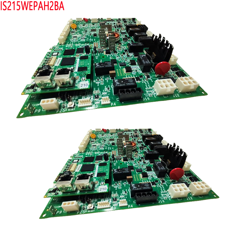
On-board signal filtering, isolation, analog-to-digital conversion, and preprocessing before uploading to the CPU for AVR automatic voltage regulation calculation.
III. Analog Output Function (Excitation Closed-Loop Regulation Drive)
0–20mA standard regulation output to drive the phase-shift control loop of the excitation power unit, regulating the excitation current and maintaining a constant turbine terminal voltage;
Output of reactive power regulation setpoint and power factor regulation setpoint signals;
Transmission of unit operating parameters to the central control DCS.
IV. Digital Switch Inputs (DI) (Status Feedback Acquisition)
Excitation Power Cabinet: Fan start/stop, rectifier bridge operation, fan cooling fan, disconnect switch opening/closing, cabinet door limit feedback;
Protection Circuit: Loss of excitation, overexcitation, underexcitation, rotor grounding, rectifier bridge fault, cooling fault alarm contacts;
System Interlocking: Grid connection/disconnection, emergency stop, local/remote mode, pulse fault, fuse blown signal.
V. Digital Switch Outputs (DO) (Execute Control Logic)
24VDC Relay Output: Controls excitation closing/opening, fan cooling start/stop;
Drives alarm indicator lights and audible/visual alarm circuits;
Output Trip Commands: Overexcitation trip, loss of excitation trip, rotor grounding protection trip;
Sends interlock enable/lock signals to other auxiliary control boards and terminal boards.
VI. Bus Communication Interaction Function
High-speed exchange of all I/O data with the main CPU board IS215WECAH via the VME backplane bus;
Supports IONet real-time industrial Ethernet for communication with extended I/O, touchscreens, and upper-level monitoring systems;
Forwards excitation regulation setpoints, issues protection action commands, and uploads real-time measurement points and fault codes.
VII. Online Diagnostics and Fault Self-Check Function
Power-on POST self-test detects channel short circuits, open circuits, and abnormal power supply to boards;
Real-time monitoring of the status of each AI/DI/DO channel; immediate reporting of faults such as open circuits, over-range faults, and short circuits;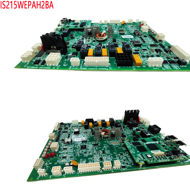
Onboard LED status indicators: PWR power, RUN operation, FAULT overall fault, and individual channel status indication;
Online monitoring of excitation circuit grounding; real-time identification of one-point/two-point grounding of the rotor;
Records fault sequence and stores channel fault logs for maintenance retrieval.
VIII. Excitation System Protection Auxiliary Processing Functions
Collects all protection contacts and sends them to the CPU to implement a complete set of excitation protection logic for over-excitation, under-excitation, loss of excitation, rotor grounding, excitation overcurrent, and rectifier bridge faults;
Quickly outputs trip, shutdown, and alarm hard contacts after protection action;
Implements preprocessing of excitation soft start, soft stop, reactive power limiting, and V/Hz limiting signals.
IX. Wind Power Dedicated Extension Functions
Compatible with the EX2100 excitation architecture of doubly-fed/direct-drive wind turbines;
Collects nacelle yaw, brake, and pitch system interlock signals;
Wide temperature range of -30℃ to 65℃ for field use, resistant to wind power electromagnetic interference, and 1500VAC isolation for surge protection.
X. Supporting and Coordinating Functions
Working with the IS215WEPAH communication board, IS200EGDMH rotor grounding sub-board, and terminal board, a complete excitation signal system is formed; it is adaptable to both single and dual redundancy architectures, with the two WEMAH boards serving as hot standby and seamless switching in redundancy mode.
Digital Switch Output (DO) Functions of this Board
I. Excitation Power Cabinet Primary Equipment Start-Stop Control Output
Excitation Rectifier Cooling Fan Start-Stop Output
Controls the power cabinet cooling fan and duct heater, with automatic switching based on temperature logic; DO disconnects and triggers an alarm when the fan fails to run.
Excitation/Flash Excitation Circuit Control (53A/53B Flash Excitation Relay Drive)
During initial unit startup, the DO output engages the flash excitation contactor, providing initial excitation power to the rotor; it automatically disconnects after voltage buildup is complete.
Excitation Main Contactor K41 Closing/Opening Drive
The output signal controls the closing and opening of the excitation main circuit, coordinating with grid connection timing to complete excitation activation/deactivation.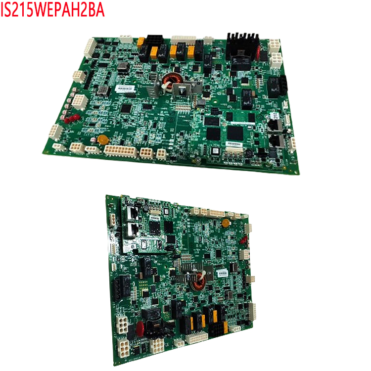
Excitation Deactivation Switch KDEP Control Output
In case of fault tripping, the output DO drives the deactivation relay, connecting the deactivation resistor to quickly release the rotor magnetic field.
II. Excitation System Fault Trip Hard Outputs (Core Safety Protection)
Excitation Overall Trip Output
Any serious fault such as overexcitation, underexcitation, loss of excitation, rotor two-point grounding, or rectifier bridge short circuit triggers DO, sending a shutdown trip hard contact.
Rotor Grounding Protection Trip Output
When paired with the IS200EGDMH grounding detection subboard, an independent DO outputs a trip command when a rotor two-point grounding is detected.
Rectifier Bridge Fault Trip Output
Thyristor overheating, fuse blowing, or cooling loss triggers DO to lock out the excitation power unit.
V/Hz Overvoltage Limiting and Overexcitation Protection Output
Outputs protection actions when terminal voltage/frequency exceeds limits, triggering unit load reduction or tripping.
External Interlocking Trip Lockout Output
After receiving interlocks for turbine/fan emergency stop, nacelle fault, or grid fault, the DO output forces demagnetization and locks excitation regulation.
III. Audible and Visual Alarms and Local Status Indicator Drive Outputs
System Comprehensive Fault Alarm DO
Outputs for any minor alarm (high temperature, disconnected circuit, abnormal fan), driving the control cabinet’s audible and visual alarms.
Operating Status Indicator Outputs
Drives excitation ready, excitation engaged, grid connection permitted, and local/remote mode indicator lights.
Separate Outputs for Different Alarm Types
Separate DO outputs for rotor grounding alarm, cooling fault, fuse fault, and regulating circuit abnormality, facilitating local fault differentiation.
IV. Unit Interlocking, Allow/Lockout Logic Output (Cross-Equipment Interaction)
Grid Connection Allow Signal Output
After excitation voltage and reactive power regulation are ready, a “Grid Connection Allowed” hard contact (DO) is sent to the generator synchronizing cabinet.
De-connection Lockout Excitation Output
Output signal at the moment of unit de-connection to limit excitation output and prevent no-load overvoltage.
Wind Turbine Auxiliary Machine Interlock Control
Direct-drive/Doubly-fed wind turbine scenario: Yaw brake allow, pitch system excitation interlock, nacelle emergency stop lockout signal.
Passive Status Transmission to DCS/Central Control System
DO drives a small intermediate relay, converting the passive dry contact to send the status to the plant’s DCS, uploading: excitation operation, excitation fault, trip, successful excitation start-up, etc.
Redundant System Master/Standby Switching Indicator Output
In a dual-redundant WEMAH architecture, when this board is the master controller, it outputs a “Local Valid” (DO) to provide switching logic to the backplane/terminal board.
V. Auxiliary Control and Diagnostic Outputs for the Regulation Circuit
Excitation Soft Start/Soft Stop Enable Output
Controls the timing of the regulation circuit’s activation to avoid excitation surges and sudden voltage drops during shutdown.
Channel Test and Simulation Test Output
Forced DO operation in maintenance mode to verify the wiring integrity of the trip and alarm circuits.
External Hard Signal Output for Board Fault
In case of power loss, CPU communication interruption, or widespread I/O channel failure, a dedicated DO output will send a “Board Failure” alarm to the higher-level controller.
DO Hardware Basic Characteristics (with Supporting Functional Constraints)
Output Level: 24VDC active transistor output, each channel drives an intermediate relay coil.
Channel Isolation: Optocoupler isolation to prevent strong excitation interference from entering the main control backplane.
Diagnostic Support: Each DO channel has readback detection; output disconnection or coil short circuit will report a FAULT fault code.
Redundancy Compatibility: In dual WEMAH hot standby mode, the faulty board’s DO is automatically disconnected, and the standby board seamlessly takes over all output logic.
Recommended related products:
IS210BPPCH1AEC
IS215WEPAH2BA
IS220PDIIH1B
IS2020JPDBG01
IS200SCTLG1A
IS200TBAOH1B
IS230TNTRH1C
IS200JGPAG1A
IS230TNTRH1C
IS200ERBPG1A
IS200TSVOH1A
IS220PAICH1A
More……
-300x300.jpg)
Reviews
There are no reviews yet.