
Description
Many products have not yet been listed online; please contact us for more information.
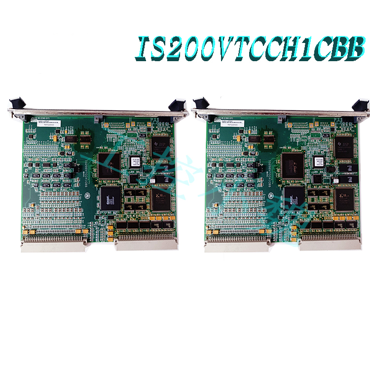
If the product model differs from the displayed image, the model number takes precedence. Please contact us for specific product photos; we can arrange for warehouse staff to take and verify them.
We operate 76 shared warehouses globally, so it may sometimes take a few hours to provide you with an accurate response; we appreciate your understanding. Rest assured, we will address your inquiries as quickly as possible.
151X1207DG06SA01 Other Names:
EX2100 Module 151X1207DG06SA01
151X1207DG06SA01 Turbine Control Unit
Input/Output Unit 151X1207DG06SA01
I. Product Overview
The 151X1207DG06SA01 is a dedicated blower module (Blower Module ASM-EX) developed by General Electric (GE) specifically for the EX2100 series excitation control system; it serves as a core component for industrial-grade forced cooling. Designed for precise temperature control within the excitation cabinet, this module provides continuous, stable cooling airflow to power electronics, control boards, and sensitive electrical components. By maintaining the system’s operating temperature within safe, rated limits, it acts as a critical component ensuring the long-term, reliable operation of the EX2100 excitation system.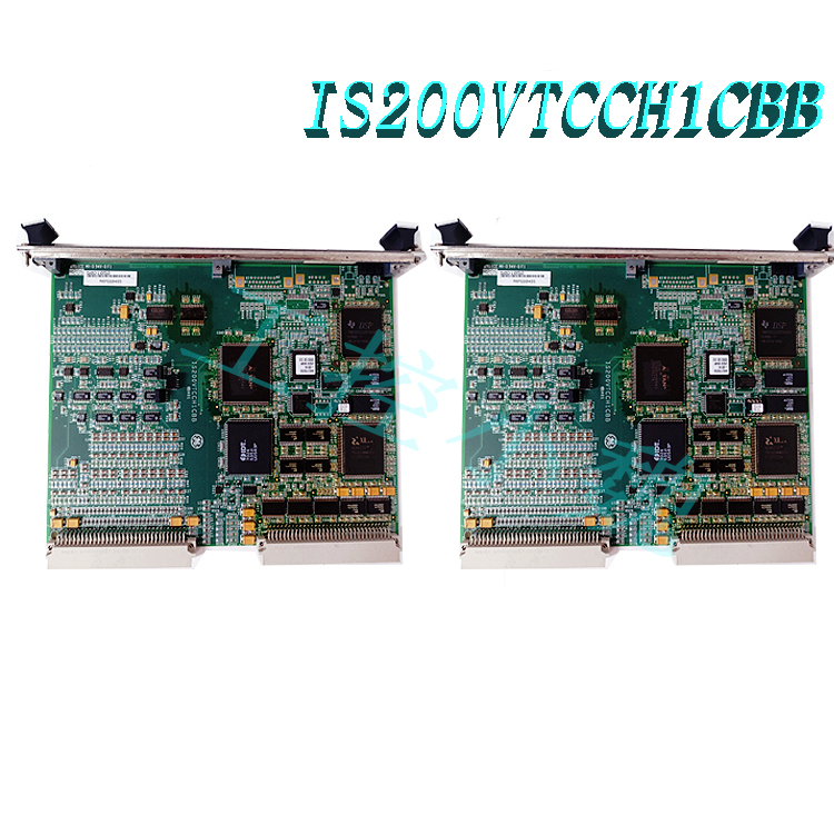
Featuring an integrated design, the product is fully compatible with the GE EX2100 excitation cabinet in terms of mounting dimensions, electrical interfaces, and airflow ducting. It allows for seamless installation without the need for modifications and serves as a standard cooling solution for excitation and drive systems in the power generation, heavy industry, and process industry sectors.
II. Operating Principle
The 151X1207DG06SA01 fan module operates based on the principle of forced convection heat transfer. It utilizes a centrifugal fan structure aligned with the system’s thermal control logic to establish a closed-loop temperature regulation system. The complete operational workflow is as follows:
Temperature Sensing and Triggering: A temperature control switch inside the excitation cabinet monitors the operating temperatures of power units (such as rectifier bridges, IGBT modules, excitation boards, and power supply modules) in real-time. When the temperature rises to a preset startup threshold, the control system sends an operation command to the fan module.
Directional Airflow Generation: The fan motor drives the centrifugal impeller to rotate at high speed, creating negative pressure at the air inlet to draw in cooler ambient air from outside the cabinet. The air is pressurized via the volute casing to form a high-pressure, directional airflow, which is then evenly delivered to the surfaces of heat-generating components through pre-configured internal air ducts.
Heat Exchange and Exhaust: As the cool airflow passes over heat sinks and circuit board components, it absorbs excess heat generated by the components through heat exchange. The heated air is then exhausted from the cabinet via the exhaust channel, ensuring continuous heat exchange and temperature control within the cabinet.
Dynamic Closed-Loop Regulation: When the internal cabinet temperature drops to a preset shutdown threshold, the temperature control signal triggers the fan to slow down or stop. This reduces energy consumption while still meeting cooling requirements, thereby achieving dynamic thermal balance within the system.
III. Key Advantages
1. OEM-Specific Design and High Integration
This module is a dedicated cooling component designed by the OEM for the GE EX2100 excitation system. Its mechanical dimensions, electrical interfaces, and airflow duct alignment are perfectly matched to the system, allowing for seamless integration without the need for modifications. This completely eliminates the risks of poor fit or compatibility issues often associated with third-party cooling accessories. 2. Industrial-grade reliability for harsh operating conditions
Constructed with high-strength, heat-resistant engineering materials and a heavy-duty, long-life bearing structure, the unit withstands harsh industrial environments characterized by high temperatures, intense vibration, and heavy dust. It supports continuous 24/7 operation, with mechanical longevity and fault resilience meeting heavy-duty industrial equipment standards, thereby significantly reducing the failure rate of the cooling system.
3. Precision cooling with superior heat exchange efficiency
The airflow path is optimized based on the heat distribution of the EX2100 system; airflow precisely targets high-heat components and sensitive control boards, ensuring balanced air distribution across the entire area and preventing localized overheating. The high-pressure airflow generated by the centrifugal structure penetrates the gaps between heat sink fins, delivering heat exchange efficiency far superior to that of standard axial fans.
4. Low vibration and noise for system stability
The module undergoes precision dynamic balancing calibration, ensuring that vibration amplitude and noise levels remain strictly within industrial standards during operation. This prevents secondary issues—such as poor board contact or signal interference—caused by fan vibration, thereby safeguarding the operational stability and measurement accuracy of the excitation control system.
5. Modular design for low O&M costs
Featuring an integrated plug-and-play modular structure, the unit allows for simple, convenient installation and replacement; in the event of a fault, the entire module can be quickly swapped out, minimizing system downtime. Routine maintenance requires only filter cleaning and fastener checks—eliminating the need for complex adjustments—and significantly reducing labor and time costs associated with operations and maintenance.
IV. Role and Value in Application Industries
The core value of the 151X1207DG06SA01 fan module lies in ensuring the reliability of upstream control systems through stable temperature regulation. Its specific roles across key industries are as follows:
1. Power Generation Industry
Used in EX2100 excitation systems for thermal, hydroelectric, and gas turbine generator units, it serves as the core thermal management component for the generator excitation control loop. By maintaining stable temperatures within the excitation power unit, it delays thermal aging of components and prevents trips caused by overheating. This ensures the stability of generator voltage regulation and reactive power control, enhances the reliability and continuity of grid power supply, and reduces the risk of unplanned power plant shutdowns.
2. Petrochemical Industry
Designed to meet the requirements for explosion-proof capabilities and long-cycle continuous production in petrochemical facilities, it provides thermal management for excitation drive equipment and turbine control systems. Its stable temperature control reduces failure rates of electronic control equipment in high-temperature environments, supports the long-term continuous operation of production units, and minimizes production interruptions and safety hazards caused by equipment overheating.
3. Iron and Steel Metallurgy Industry
Adapted to the harsh operating environments of steel plants—characterized by high temperatures, heavy dust, and intense vibration—it provides cooling for drive and excitation control systems in rolling lines and smelting equipment. It effectively withstands environmental stressors, ensures the stable operation of high-power drive equipment, and supports continuous steel production processes.
4. Papermaking and Heavy Manufacturing Industries
Applied to cooling industrial control cabinets for papermaking lines and heavy equipment, it maintains the operational stability of control systems through precise temperature regulation. This reduces production line downtime caused by thermal failure of electronic components, thereby enhancing overall production efficiency and extending equipment service life.
V. Standard Operating Procedures
(I) Installation Procedures
Safe Power Disconnection: Before installation, disconnect the cabinet’s main power and control power supplies. Implement the “Lockout/Tagout” (LOTO) procedure and verify the absence of voltage using testing equipment before proceeding.
Positioning and Securing: Align the 151X1207DG06SA01 fan module with the cabinet’s designated mounting slots and fixing holes. Secure the module using the supplied bolts, tightening them evenly in a diagonal pattern to ensure a tight seal against the cabinet’s air duct, leaving no gaps for air leakage.
Electrical Wiring: Refer to the manufacturer’s wiring diagram to connect the power supply terminals, temperature control signal terminals, and grounding terminals in sequence. Ensure all connections are secure and the wiring order is correct. Route signal cables separately from power cables to prevent electromagnetic interference.
Post-Installation Check: Manually rotate the fan impeller to ensure there is no binding or abnormal friction noise. Verify that the air inlets and outlets are unobstructed and that the module housing shows no deformation or damage.
(II) Commissioning Procedures
Pre-Power-Up Verification: Re-verify wiring correctness, remove any tools or debris left inside the cabinet, and close all cabinet doors and ventilation baffles.
Jog Test: Briefly apply control power to perform a jog test. Observe the impeller rotation direction to ensure it matches the direction indicated on the module. Confirm the absence of abnormal noise or vibration, then immediately disconnect the power.
Load Test: Start the EX2100 excitation system and operate it under rated load. Monitor temperature changes at key points within the cabinet, verify the accuracy of the temperature setpoints for fan start/stop operations, and check that the airflow at the outlet meets design specifications.Signal Commissioning: Verify that the fan’s operating status and fault alarm signals are correctly transmitted to the main control system, and that remote start/stop functions trigger and respond correctly.
(III) Daily Operation
Startup: Under normal operating conditions, the fan module powers up synchronously with the excitation system; startup and shutdown are automatically controlled by the system’s temperature control logic, requiring no manual intervention.
Operational Inspection: Periodically inspect the fan for abnormal noise or vibration; check that the cabinet air intake filters are free of clogs and the air outlets are unobstructed; and verify that the system temperature reading is within the normal range.
Shutdown: Simply power down the unit along with the excitation system. For long-term shutdowns, cover the air intake and outlet after the fan has come to a complete stop to provide dust protection.
VI. Safety and Maintenance Precautions
1. Safe Operating Procedures
All inspection and maintenance tasks must be performed only after the power has been completely disconnected and verified as off. Disassembling the module or touching internal rotating parts while the unit is energized is strictly prohibited.
Do not insert hands, tools, or other foreign objects into the air intake or outlet while the equipment is running to prevent mechanical injury or equipment damage.
The casing and air outlet reach high temperatures during operation; avoid direct contact to prevent burns.
2. Operating Environment Requirements
The recommended operating temperature range for the module is 0°C to 60°C; additional temperature control measures are required if the temperature falls outside this range.
Keep the installation environment dry and clean; prevent corrosive gases, excessive dust, and conductive particles from entering the fan, as these can cause component corrosion or bearing wear.
Do not stack items near the cabinet air intake or outlet; ensure unobstructed airflow and do not block ventilation paths. 3. Routine Maintenance Points
Periodic Cleaning: Clean the intake filter screen and remove dust accumulation from the impeller every 1 to 3 months, depending on the dust levels in the operating environment, to prevent increased air resistance and reduced heat dissipation efficiency.
Fastener Inspection: Inspect mounting bolts and wiring terminals every six months to prevent loosening caused by prolonged vibration, which could lead to poor electrical contact or equipment detachment.
Bearing Maintenance: Replenish bearing grease according to manufacturer specifications once the rated operating duration is reached; shut down the unit and replace bearings immediately if abnormal noise occurs or vibration levels exceed limits.
Fault Handling: Immediately shut down and inspect the unit if the fan exhibits abnormal noise, excessive vibration, insufficient airflow, or fails to start; do not force the unit to operate before the fault is resolved.
Spare Parts Replacement: When replacing faulty modules, prioritize using original manufacturer parts of the same model to ensure heat dissipation performance and system compatibility, avoiding the use of mismatched parts that could cause system overheating.
Recommended related products:
151X1225DF01PC03
151X1225DF01PC03RA
DS3820HSPB
151X1215DC20SA01
151X1215DC21MG01
151X1225DE18PC05
IPU2-MA65490100A-D100789
VEGA VEGASTAB TYPE-570.07 8342-20
VPU-A413310
PUD-2-542829-3A-M8513011
More……

Reviews
There are no reviews yet.