
Description
Many products have not yet been listed online; please contact us for more information.
If there is a discrepancy between the product model and the displayed image, the model number takes precedence. Please contact us for specific product photos; we can arrange for warehouse staff to take and send confirmation images.
We operate 76 shared warehouses globally; consequently, it may sometimes take a few hours to provide you with an accurate response. We appreciate your understanding and assure you that we will address your inquiries as quickly as possible.
I. Product Overview and Model Relationships
The EMERSON VE3008, CE3008, and KJ2005X1-MQ1 are core control units designed for use within the Emerson DeltaV Distributed Control System (DCS). Their roles and interrelationships are as follows:
KJ2005X1-MQ1 is the official material code corresponding to the physical product VE3008—the DeltaV MQ series core controller module—which serves as the computational and control heart of the control node.
CE3008 is the associated controller carrier and communication base unit. It provides power input, backplane bus connectivity, network interface expansion, and physical mounting support for the VE3008; the two components work together to form a complete field control station node.
This controller assembly is a high-performance, modular control unit developed by Emerson for the process industry. It features real-time computing, multi-protocol communication, redundancy and fault tolerance, and intelligent diagnostic capabilities, making it widely suitable for industrial automation applications that demand rigorous stability and real-time performance.
2. Core Operating Principles
2.1 Core Operating Principles of the VE3008 (KJ2005X1-MQ1) Controller
As the central processing unit of the control node, the VE3008 operates based on a closed-loop logic cycle: data acquisition, computational control, command output, and network interaction.
Field Data Acquisition and Interaction: It connects to the backplane I/O bus via the CE3008 carrier, automatically identifying attached I/O modules. It acquires real-time field signals—such as analog and digital inputs, temperature, and pressure—while outputting control commands to actuators; a single controller can manage hundreds of I/O points.
Control Algorithm Execution: Equipped with a high-performance microprocessor, it supports various control modes, including continuous PID regulation, logic interlocking, sequential control, and batch control. With a scan cycle as fast as 100ms, it achieves high-precision closed-loop control of industrial processes.
Network Communication and Data Exchange: It connects to the DeltaV control network via dual-redundant RJ45 Ethernet interfaces. It uploads real-time data and alarm information to host computers and engineering stations while receiving configuration parameters and control commands. It also supports multiple industrial protocols—such as Modbus TCP/IP, HART, and Profibus-DP—enabling data interoperability with third-party devices.
Redundant Hot-Standby Mechanism: It supports a dual-controller hot-standby architecture, with real-time mirroring of operational data and configuration settings between the primary and standby controllers. In the event of a primary controller failure, the standby controller can seamlessly take over control within 50ms without disrupting field process operations.
2.2 CE3008 Communication Base Operating Principle
The CE3008 serves as the physical mounting platform and communication hub for the controller, performing three core functions: connection, power supply, and signal conversion.
It provides a standard backplane interface to facilitate electrical connections and data transmission between the VE3008 controller, I/O modules, and power supply modules.
It connects to the system power supply to provide stable DC power to the controller and associated I/O modules, featuring an integrated, non-replaceable 3.0A fuse for overcurrent protection.
It extends network and bus interfaces, performing protocol conversion between control network signals and backplane bus signals to ensure stable data transmission across devices at different levels.
III. Core Technical Advantages
3.1 Highly Reliable, Fault-Tolerant Design Ensuring Continuous Process Operation
Utilizing a fully redundant architecture, it supports triple redundancy—controller, network, and power supply—with a failover time of less than 50ms and no interruption to control operations. Built-in self-diagnostic functions accurately pinpoint hardware faults, significantly reducing the risk of unplanned downtime and achieving up to 99.99% availability in critical process applications.
3.2 High-Performance Real-Time Control Meeting High-Precision Process Requirements
It supports a control scan cycle as fast as 100ms and a control resolution of ±0.01%, enabling precise control of rapidly changing process parameters such as pressure, flow rate, and liquid level. With 48MB of user memory, it accommodates complex control logic and batch programs, meeting the control requirements of large- and medium-scale production facilities.3.3 Multi-protocol compatibility for flexible adaptation to industrial scenarios
Native support for mainstream industrial protocols—such as Ethernet, Modbus, HART, Foundation Fieldbus, and Profibus—enables seamless integration with various smart instruments, variable frequency drives (VFDs), analytical instruments, and third-party control systems. A modular design allows for the on-demand expansion of I/O points and function cards, accommodating control scales ranging from small process sections to entire plant-wide operations.
3.4 Industrial-grade environmental adaptability for stable performance in harsh conditions
The system supports wide-temperature operation (ranging from -40°C to +70°C) and features an IP20 protection rating. It complies with hazardous area certifications such as ATEX, IECEx, and FM, ensuring long-term, stable operation in harsh industrial environments characterized by high vibration, strong electromagnetic interference, and heavy dust.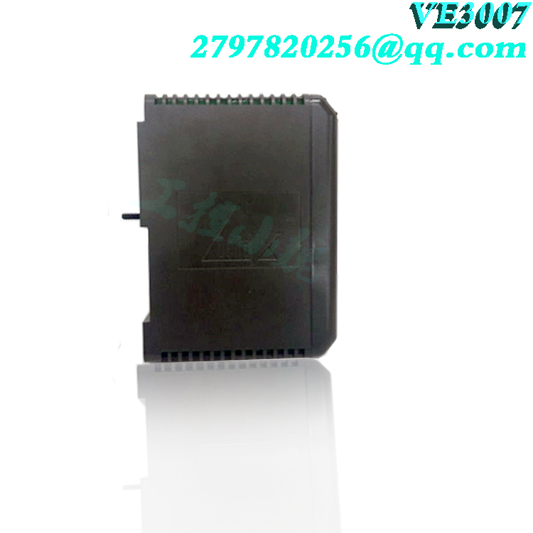
3.5 Ease of deployment and maintenance to reduce total lifecycle costs
Plug-and-play installation allows the controller to automatically identify I/O cards and assign addresses, eliminating the need for manual configuration. Hot-swapping capabilities enable module replacement without interrupting system operation. Built-in LED status indicators facilitate rapid diagnosis of power, operational, and fault states, thereby reducing maintenance complexity and time costs. Additionally, compatibility with legacy systems like PROVOX and RS3 enables smooth upgrades, protecting the user’s existing hardware investment.
IV. Core value across application industries
4.1 Petrochemical industry
In applications such as oil refining, ethylene production, and fine chemical processing, the VE3008/CE3008 controller enables precise closed-loop control and safety interlock protection for reactors, distillation columns, and pump/valve units. This stabilizes process parameters while reducing material waste and energy consumption. Furthermore, a redundant architecture ensures the continuous operation of high-risk processes, mitigates safety risks, and meets the petrochemical industry’s stringent requirements for explosion protection and high reliability. 4.2 Electric Power and Energy Industry
Applied to unit control and auxiliary systems in thermal, hydroelectric, and renewable energy power plants, it enables coordinated control of boiler combustion, steam turbine speed regulation, and generator excitation, thereby optimizing load response speed and enhancing power generation efficiency. It supports integration with SCADA and EMS systems, facilitating automated dispatching and intelligent O&M for power plants.
4.3 Metallurgy and Mining Industry
Designed for processes such as blast furnace operations, steel rolling, and mineral processing, it ensures stable control of parameters (temperature, pressure, rotational speed, etc.) and equipment interlocking protection, thereby improving the pass rate of metallurgical products. Its wide-temperature, vibration-resistant hardware design is suitable for the harsh operating conditions of mines and steel plants, reducing equipment downtime and enhancing production continuity.
4.4 Biopharmaceutical Industry
Meets the high-precision and strict compliance requirements of pharmaceutical manufacturing by enabling precise control of temperature, pressure, and flow rates during processes such as fermentation, extraction, and formulation, ensuring batch consistency and traceability. It complies with standards for cleanrooms and explosion-proof zones, supporting GMP-compliant management of pharmaceutical production.
4.5 Water Treatment and Environmental Protection Industry
Applied in scenarios such as municipal sewage treatment, industrial wastewater treatment, and flue gas desulfurization and denitrification, it automates processes like chemical dosing, aeration, and filtration. This stabilizes effluent quality while reducing energy consumption and chemical usage. It also supports remote monitoring, improving the O&M efficiency and compliance rates of environmental protection facilities.
4.6 Food and Beverage Industry
Meets the sanitary control requirements of food production by automating processes such as filling, sterilization, and cold chain management, ensuring production efficiency and consistent product quality. It supports batch recipe management and accommodates product changeovers, helping food enterprises achieve flexible production.
5. Standard Operating Procedures
5.1 Installation and Power-Up
Ensure the system is powered off and the Lockout/Tagout (LOTO) procedure is followed; implement anti-static measures. Secure the CE3008 base into the corresponding slot on the power/controller carrier and verify a firm connection to the backplane.
Align the VE3008 (KJ2005X1-MQ1) controller with the slot on the CE3008 base and insert it steadily; ensure the locking mechanism is engaged and the physical installation is complete.
Connect the RJ45 Ethernet cables for the primary and redundant control networks, ensuring secure connections.
Turn on the system power switch and observe the controller panel indicators: a steady green “Power” light indicates normal power supply; a steady green “Active” light indicates the controller has entered the primary operating state; a steady green “Standby” light indicates the controller is in standby mode.
5.2 Configuration and Program Download
Open the DeltaV Explorer configuration software on the engineering station; create a new project or open an existing one for the corresponding control station, and configure the controller IP address, I/O card points, and control logic.
Upon completion of configuration, perform a compile and verify operation to ensure there are no logic errors or parameter anomalies.
Select the target controller node and execute the “Download” command to transfer the configuration program and parameters to the VE3008 controller; monitor the indicator lights during the download process, and note that the controller automatically enters operating mode once the download is complete.
Verify online that data acquisition and control outputs for all points are functioning correctly and confirm that the control logic executes as expected.
5.3 Routine Operational Monitoring
Use the DeltaV operator station to monitor the controller’s operating status, process parameters, and alarm information in real-time, paying particular attention to the stability of setpoints, process values, and output values within the control loops. Enter the system diagnostics interface to check the controller’s CPU load, memory usage, communication status, and redundancy status, ensuring there are no fault alarms.
If control parameters need modification, perform the changes online using engineer-level privileges; verify that the process response is normal after the changes and document the parameter modifications.
5.4 Redundancy Switchover Operations
Manual redundancy switchover can be performed under normal operating conditions: select the standby controller in the configuration software and click “Switch to Primary Controller”; the system will complete the role swap between primary and standby units without process disturbance.
Monitor field device status during the switchover to ensure process parameters remain stable; after the switchover, verify that the new primary controller is operating correctly and data communication is functioning properly.
If the primary controller fails, the system will automatically trigger a switchover; maintenance personnel must promptly diagnose the cause of the failure, repair the unit, and return it to hot-standby status.
5.5 Shutdown and Replacement Operations
Before shutdown, confirm that the process has reached a safe state and that all control loops have been switched to manual or local control mode.
Stop the controller operation via the software and disconnect the power supply for the corresponding system loop.
Release the locking mechanism to remove the faulty controller, install a spare unit of the same model, restore power, download the backed-up configuration program, and switch back to automatic control mode after verifying normal operation.
VI. Installation, Operation, and Maintenance Precautions
6.1 Installation Safety Precautions
Installation and replacement must be performed by professionals trained on the Emerson DeltaV system. Implement anti-static measures throughout the process—such as wearing an anti-static wrist strap—to prevent electrostatic damage to precision electronic components.
Strictly adhere to power-off and Lockout/Tagout (LOTO) procedures; hot-swapping the controller or base module is strictly prohibited to prevent damage to the backplane circuitry. Ensure the cabinet and system are properly grounded, with grounding resistance meeting industrial automation system specifications, to prevent electromagnetic interference from affecting communication stability.
The installation location must be away from sources of strong vibration, intense electromagnetic radiation, and high heat; ensure sufficient space is reserved for heat dissipation.
6.2 Precautions for Operation and Commissioning
Before initial startup, verify that the controller firmware version is compatible with the DeltaV system version to avoid communication anomalies or functional mismatches.
Always back up the existing controller program and parameters before downloading the configuration to prevent data loss; do not cut off power during the download process to avoid damaging the controller firmware.
For redundant systems, perform a primary-to-backup switchover test before startup to verify that the switchover causes no process disturbances or fluctuations; proceed to formal operation only after confirming the redundancy function is operating correctly.
Adjust control parameters gradually; avoid aggressive parameter settings that could cause process oscillations or equipment damage.
6.3 Precautions for Routine Maintenance
Regularly check controller indicator lights and system diagnostic alarms; promptly address warning messages regarding communication anomalies, high temperatures, etc.
Clean the controller surface and cabinet ventilation holes every six months to prevent dust accumulation from impairing heat dissipation; disconnect power before cleaning and use dry, anti-static tools.
Regularly back up controller configuration programs and system settings; store backups at an off-site location to ensure rapid recovery in the event of a failure.
For controllers in long-term operation, it is recommended to periodically conduct redundancy switchover drills to verify the availability of the backup controller.
6.4 Basic Troubleshooting Guidelines
When a fault occurs, first check the panel indicator lights and system diagnostic information to preliminarily identify the fault type (power supply, communication, hardware, or configuration).
For communication faults, prioritize checking network cable connections, IP configurations, and network node status; for control faults, prioritize checking configuration logic and field I/O devices.
Hardware faults can be quickly resolved by replacing the unit with a spare part of the same model; the faulty module should be returned to the factory for inspection and repair. Unauthorized disassembly or repair is strictly prohibited.
Model recommendation:
EMERSON Detection module A6120
EMERSON 9199-00002 A6120
EMERSON Detection module CSI3120
EMERSON A3120/022-000 CSI3120
EMERSON FLOBOSS S600+ Panel Mount Fiscal Flow Computer
PR6423/010-040 CON021 8mm Eddy Current Displacement Sensor System EMERSON
EMERSON MMS6120 Electric Sensor Bearing Vibration Monitor
EMERSON VGA-12-9242-240-506B PCB CARD
Emerson 5X00846G01 Ovation Analog Input Modules
Emerson 5X00846G01 Ovation Series 8-Channel Fast HART Analog Output Module
Emerson 5X00594G01 Ovation Analog Input Modules
Emerson 5X00790G01 Ovation Analog Input Module
Emerson 5X00790G01 Ovation Analog Input Module
Emerson 5X00594G01 Ovation Analog Input Modules
EMERSON A6110 9199-00001
More……
admin –
Installation, Operation, and Maintenance Precautions
6.1 Installation Safety Precautions
Installation and replacement must be performed by professionals trained on the Emerson DeltaV system. Implement anti-static measures throughout the process—such as wearing an anti-static wrist strap—to prevent electrostatic damage to precision electronic components.
Strictly adhere to power-off and Lockout/Tagout (LOTO) procedures; hot-swapping the controller or base module is strictly prohibited to prevent damage to the backplane circuitry. Ensure the cabinet and system are properly grounded, with grounding resistance meeting industrial automation system specifications, to prevent electromagnetic interference from affecting communication stability.
The installation location must be away from sources of strong vibration, intense electromagnetic radiation, and high heat; ensure sufficient space is reserved for heat dissipation.
6.2 Precautions for Operation and Commissioning
Before initial startup, verify that the controller firmware version is compatible with the DeltaV system version to avoid communication anomalies or functional mismatches.
Always back up the existing controller program and parameters before downloading the configuration to prevent data loss; do not cut off power during the download process to avoid damaging the controller firmware.
For redundant systems, perform a primary-to-backup switchover test before startup to verify that the switchover causes no process disturbances or fluctuations; proceed to formal operation only after confirming the redundancy function is operating correctly.