
Description
All products on this site are specialized items subject to fluctuating market prices;
please rely on the quote provided by customer service, as the listed price may not be the actual current price;
please confirm details—such as the model, product specifications, and price—with customer service before placing an order;
please contact customer service for inquiries regarding availability.
RS-FS-9001 362A1052P004 – Alternative Names:
Ultraviolet (UV) Flame Detector RS-FS-9001 362A1052P004
RS-FS-9001 362A1052P004 GE Gas Turbine System
The RS-FS-9001 362A1052P004 is a UV flame sensor from the Reuter-Stokes “Flame Tracker™” series (originally under GE, now manufactured and sold by Baker Hughes). “362A1052P004” is the order number; the “P” suffix indicates the version (this series includes iterations such as P001, P004, and P404; interfaces and mounting dimensions are generally compatible, though the specific unit’s nameplate should be consulted for on-site verification). Essentially, it consists of a solid-state UV detection head with a viewing window combined with a two-wire transmitter; its core component is a silicon carbide (SiC) photodiode, rather than an older-style UV counting tube.
Physically, it utilizes “solar-blind” solid-state UV detection, meaning it responds only to flames and ignores hot backgrounds; regarding interfaces, it uses a two-wire 4–20 mA signal, allowing for flame-out interlock functions when connected to a combustion management system; on-site requirements dictate a sealed, non-disassemblable unit, a clean viewing window, and adherence to safety protocols for explosion-proof zones.
I. Functions
Its functions can be summarized in four points.
First, flame presence detection. It monitors the presence of flame within the burner or gas turbine combustion chamber in real time. This result is transmitted directly to the Burner Management System (BMS) for ignition confirmation and flame-out protection, serving as a core input for the overall fuel interlocking circuit.
Second, it provides continuous measurement of flame intensity. Its output is not a simple binary “flame on/off” signal but a 4–20 mA current signal; the current magnitude is directly proportional to the ultraviolet (UV) intensity of the flame (approximately 4 mA corresponds to no flame, while 20 mA corresponds to a strong flame, with an upper limit not exceeding 21 mA). This allows the system to monitor flame intensity trends and detect combustion deterioration early.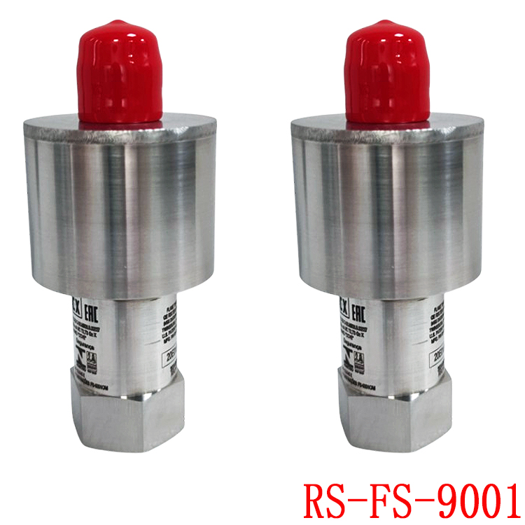
Third, it adapts to a wide dynamic range. The sensor features a high initial gain in its internal amplification stage, which automatically switches to low gain as light intensity increases. Consequently, it can measure everything from a faint pilot flame to a full-load blaze without signal saturation or distortion.
Fourth, it offers diagnostic capabilities. The two-wire current loop offers a distinct advantage: if the circuit opens, the current drops immediately to 0 mA. This allows the system to instantly distinguish between a “sensor circuit fault” and a “flame-out” condition, facilitating troubleshooting.
II. Advantages
First, strong interference immunity—this is its most prominent selling point. The SiC photodiode responds to the 200–400 nm ultraviolet range and is virtually unresponsive to visible light or infrared radiation. Since incandescent furnace walls and refractory bricks primarily emit infrared radiation, and ambient lighting or sunlight consists mainly of visible light, these sources do not trigger false alarms; only actual combustion flames activate the sensor.
Second, “solar-blind” characteristics. Ultraviolet rays with wavelengths shorter than 300 nm are absorbed by the atmospheric ozone layer and do not reach the ground. Therefore, the sensor does not generate false signals due to sunlight, even in bright outdoor daylight environments.
Third, a robust and durable structure. The housing is made of fully welded AISI 304 stainless steel and argon-purged for internal protection; it withstands pressures up to 400 psi (approx. 2.8 MPa), enabling it to endure combustion chamber pressures and harsh operating environments.
Fourth, it offers a wide temperature operating range. The official quick-start guide specifies an operating range of -40°C to +150°C; when paired with a water-cooling jacket for high-temperature conditions, it meets the demands of environments characterized by high heat and intense radiation, such as gas turbines.
Fifth, it boasts high reliability. Being all-solid-state with no moving mechanical parts, the series has accumulated over 500 million hours of operation according to official data; the design philosophy is essentially “install and forget.”
Sixth, it is explosion-proof certified. It holds North American Class I Div 2 and Zone 2 certifications, as well as ATEX and IECEx certifications (Increased Safety “e” type), allowing for direct use in hazardous areas.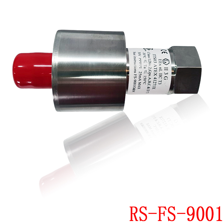
Seventh, wiring and power supply are straightforward. It utilizes a two-wire system where power and signal share the same pair of wires; it operates on 24V DC (compatible with a wide 12–30V range), resulting in low on-site installation costs.
III. Applications
Its most typical application is flame monitoring and flame-out protection for GE’s own gas turbines, widely used in both the Frame and LM series. It is also used for:
Burner management in heat recovery steam generators (HRSG) and power plant boilers; ignition confirmation and flame-out interlocking for industrial burners, process heaters, and petrochemical tube furnaces; and flame monitoring in hazardous areas requiring explosion-proof certification (using a water-cooling jacket in high-temperature, high-radiation environments).
It is suitable for any scenario involving fuel combustion where a flame is required and fuel must be cut off immediately upon flame loss.
IV. Precautions
There are eight points to keep in mind for on-site use; the first two concern safety, while the others directly impact reliability. First, connecting or disconnecting the connector while the power is on is strictly prohibited in hazardous areas. The official warning explicitly states there is an “explosion risk”; you must ensure the environment is safe and cut off the power before proceeding.
Second, certified cables—specifically the RS-E2-0285 or GE 362A1053Pxxx series—must be used, and wiring must be routed through grounded metal conduit. The green/yellow wire must be grounded at the field junction box, while the shield must be grounded at a single point (the controller end only); intermediate grounding or short-circuiting between wires is not permitted.
Third, disassembling the sensor is strictly prohibited. It is internally sealed and filled with argon gas; if the seal is broken and the gas escapes, the unit is rendered useless and cannot be repaired. During installation, use the dedicated 1-3/8 inch mounting nut; never attempt to tighten it by gripping the sensor body itself, as this will damage the seal.
Fourth, the window is the “lifeline.” Ultraviolet signals can be severely attenuated by oil, dust accumulation, or coking, leading to false flame-out indications. Clean the window with an isopropyl alcohol swab during every maintenance check, and apply NEVER-SEEZ NG-165 anti-seize compound to the mounting threads.
Fifth, a water-cooling jacket is mandatory for high-temperature applications. The tightening torque for the cooling jacket clamp is 50–60 lb-in (approx. 5.6–6.8 N·m); re-tighten it after the first shutdown. Also, ensure the edge of the metal band does not rub against the cooling pipe.
Sixth, ensure correct wiring polarity. The white wire is positive and the black wire is negative; reversing them won’t burn out the sensor, but it will prevent it from functioning. Always verify this after a new installation.
Seventh, use a UV flashlight (wavelength range: 245–365 nm) for field testing; a standard visible-light flashlight will not trigger the sensor. This is a common mistake made by new colleagues.
Eighth, verify the maximum operating temperature against the final specifications. Temperature ratings vary depending on the model and cooling method; do not operate the unit beyond its limits.
V. Operating Principle
Finally, let us explain the operating principle using a signal chain.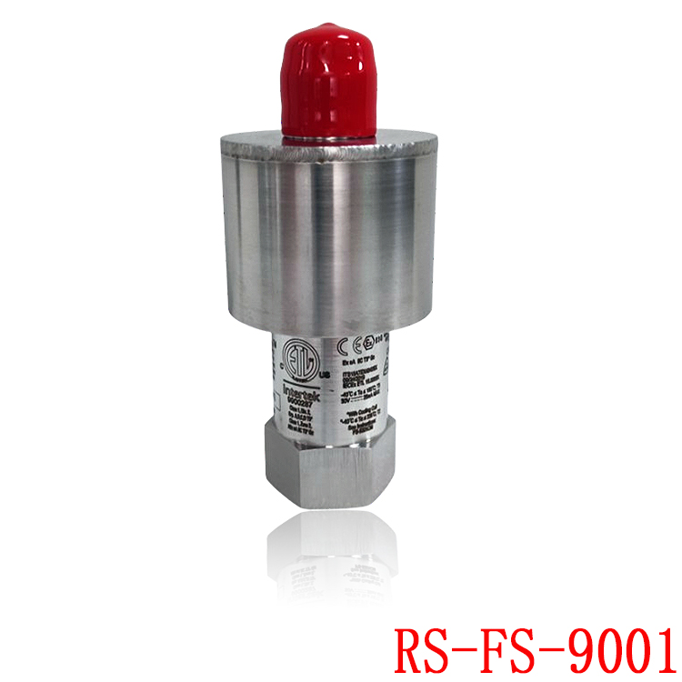
Step 1: Flame generation of characteristic ultraviolet radiation. During gas or oil combustion, OH radicals within the flame emit a strong, characteristic ultraviolet spectral band near 306–310 nm. This corresponds to the wavelength used for the sensor’s sensitivity calibration: the specified sensitivity is greater than 5 mA, corresponding to an irradiance of 1 × 10⁷ photons per square inch per second at a wavelength of 310 nm.
Step 2: Light transmission through the sapphire window. The window is made of sapphire, which offers high UV transmittance, high-temperature resistance, and corrosion resistance; it isolates the sensor’s interior from the high-temperature flue gases in the combustion chamber while allowing ultraviolet light to pass through.
Step 3: Photoelectric conversion via a silicon carbide (SiC) photodiode. Incident UV photons strike the SiC p-n junction, generating electron-hole pairs and producing a photocurrent proportional to the light intensity. This is the physical basis for the “solar-blind” characteristic: SiC is sensitive only to UV light in the 200–400 nm range and does not respond to visible or infrared light. Since short-wave UV from sunlight is blocked by the ozone layer, the sensor naturally responds only to the UV emitted by the flame, ignoring thermal background radiation.
Step 4: Adaptive gain amplification. The amplification stage starts with high gain and automatically reduces it as light intensity increases, ensuring linear operation across the entire range from small to large flames.
Step 5: Two-wire current loop output. The sensor modulates the supply current into a 4–20 mA signal proportional to the UV intensity. Power and signal share a single pair of wires, with the control unit providing 12–30 V DC power. The control unit uses a sampling resistor to convert the current into a voltage signal for the combustion management system; the system uses this to determine the presence and intensity of the flame and executes a fuel cut-off interlock in the event of flame failure. If the current loop opens and the current drops to 0 mA, the system can still diagnose a loop fault based on this.
Model recommendation:
CC-PAOH01
CC-IP0101
CC-IP0101 51410056-175
CC-MCAR02
CC-PAIH01 51405038-175
CC-PAIH01
CC-PAIH02
CC-PAIH51 51410069-275
CC-PAIH51
CC-PAIM01 51405045-175
TC-PPD011
TC-ODK161
TC-FPCXX2
TC-CCR014
05701-A-0502
05701-A-0301
05701-A-0451
05701-A-0327
05701-A-0283
05701-A-301ISS
05701-A-0288
05701-A-0294
05704-A-0123
05704-A-0146
More……
-300x300.jpg)
admin –
II. Product Positioning and Application Scenarios
Designed specifically for gas turbines, industrial boilers, heating kilns, and combined cycle gas turbine power plants, this sensor continuously monitors the main combustion/ignition flame and quickly triggers fuel cut-off protection upon flameout. It is a core sensor for gas turbine safety interlocking.
Compatible Fuels: Natural gas, heavy oil, light oil, and mixed gases
Replacement Compatibility: Directly replaces older models 362A1052P404 and 362A1052P001; mechanical and electrical compatibility is complete.
III. Core Detection Principle
Utilizing a SiC (silicon carbide) ultraviolet photodiode, it captures the flame’s unique ultraviolet spectrum, unaffected by visible light from the furnace, high-temperature infrared radiation, or furnace reflections. It also exhibits strong resistance to high-temperature smoke and strong background light interference.
Detection Distance: Maximum 9 meters (30 feet)
Response Speed: Typical <50ms, ultra-fast flameout detection, eliminating the risk of deflagration
IV. Electrical Specifications
Power Supply: 24VDC (±10%) two-wire circuit
Signal Output: Standard 4–20mA current loop
4mA: Sensor fault/open circuit
12mA: No flame
20mA: Stable flame detected
Power Consumption: Low-power circuit design, compatible with gas turbine PLC/flame amplifier systems
Cable: Dedicated shielded high-temperature resistant cable, suppressing interference from frequency converters and high-voltage ignition
V. Mechanical and Environmental Parameters
Housing Material: AISI 316 stainless steel body, sapphire optical window
Mounting Thread: 3/4 inch NPT standard thread, compatible with gas turbine observation sleeve
Operating Ambient Temperature: -20℃ ~ +85℃; with air cooling for short-term tolerance 150℃
Protection Rating: IP66, dustproof and waterproof, suitable for outdoor gas turbine nacelles
Humidity: 5%~95% RH, non-condensing
Vibration Resistance: 5~200Hz industrial vibration withstand, suitable for high-speed vibration conditions of gas turbines
VI. Explosion-proof Safety Certification
ETL, ATEX, IECEx, Class I Division 2 explosion-proof certification, suitable for use in areas with hazardous gas and oil explosions.
VII. Supporting Control Systems
GE Mark VI / Mark VIe Gas Turbine Control System (Most Commonly Used)
Various 4–20mA Input Flame Amplification Modules, Boiler Combustion Management System (BMS)
Supports remote loop self-test; the system can identify probe dirt, open wires, and short circuit faults.
VIII. Maintenance and Spare Parts Considerations
Regular Maintenance: Periodically clean the sapphire window; carbon buildup will reduce the flame signal and cause false no-flame alarms.
Spare Parts Differentiation: Parts with suffixes P004/P104/P404 have the same hardware appearance, but internal firmware is compatible with different gas turbine models. Replacement should prioritize parts with the same suffix.
Common Causes of Failure: Window dust accumulation, cooling air interruption leading to overheating, damaged shielded cable, excessive 24V power supply voltage drop.
IX. Differentiation Within the Same Series
RS-FS-9001 (362A1052P004): Pure UV, standard gas turbine model
RS-FS-9010: UV + Wide visible light spectrum, long-distance monitoring of large boilers
RS-FS-9001-H: High-temperature enhanced version, for use in kilns without cooling ducts
https://www.weikunfadacai1.com/product/rh924uq-foxboro/
https://www.weikunfadacai1.com/product/3bhe030579r0003-controller-abb/
https://www.weikunfadacai1.com/product/unitrol-1020-controller-abb/
https://www.weikunfadacai1.com/product/abb-unitrol-1020-uns0119a-zv1-3bhe030579r0003/
https://www.weikunfadacai1.com/product/unitrol-1020-3bhe030579r0003/
https://www.weikunfadacai1.com/product/abb-unitrol-1020-3bhe030579r0003/
https://www.weikunfadacai1.com/product/362a1052p004-flame-detector-honeywell-362a1052p004/
admin –
The 362A1052P004 is an industrial ultraviolet (UV) flame detector/scanner originally designed for gas turbine fireboxes (e.g., GE Mark V/VI/VIe systems) and manufactured or cross-referenced within the industrial combustion monitoring product line.
**Key Specifications and Functions**
**Sensing Technology:** Utilizes UV-sensitive principles (depending on the specific version, employing a Geiger-Miller cold cathode tube or an advanced silicon carbide (SiC) UV photodiode) to detect the UV spectrum of hydrocarbon flames.
**Applications:** Real-time monitoring of gas turbine burners, industrial boilers, and petrochemical furnaces.
**Compatibility:** Directly replaces legacy components, and the 362A1052P004 possesses full mechanical and electrical compatibility with the 362A1052P404.
**Certifications:** Typically has hazardous area explosion-proof ratings such as ATEX, IECEx, and Class I Division 2.
Maintenance and Troubleshooting
Window Cleaning: Regular maintenance requires cleaning the sapphire/optical windows; carbon or dust buildup can block UV light transmission and trigger false “no flame” alarms.
Cooling: A proper cooling air/water system is required to prevent the high-temperature turbine casing from overheating.
admin –
Its functions can be summarized in four points.
First, flame presence detection. It monitors the presence of flame within the burner or gas turbine combustion chamber in real time. This result is transmitted directly to the Burner Management System (BMS) for ignition confirmation and flame-out protection, serving as a core input for the overall fuel interlocking circuit.
Second, it provides continuous measurement of flame intensity. Its output is not a simple binary “flame on/off” signal but a 4–20 mA current signal; the current magnitude is directly proportional to the ultraviolet (UV) intensity of the flame (approximately 4 mA corresponds to no flame, while 20 mA corresponds to a strong flame, with an upper limit not exceeding 21 mA). This allows the system to monitor flame intensity trends and detect combustion deterioration early.
https://www.weikunfadacai1.com/product/abb-pp881-3bse092978r1/
https://www.weikunfadacai1.com/product/362a1052p004-flame-detector-honeywell-362a1052p004/
admin –
The RS-FS-9001 362A1052P004 is a UV flame sensor from the Reuter-Stokes “Flame Tracker™” series (originally under GE, now manufactured and sold by Baker Hughes). “362A1052P004” is the order number; the “P” suffix indicates the version (this series includes iterations such as P001, P004, and P404; interfaces and mounting dimensions are generally compatible, though the specific unit’s nameplate should be consulted for on-site verification). Essentially, it consists of a solid-state UV detection head with a viewing window combined with a two-wire transmitter; its core component is a silicon carbide (SiC) photodiode, rather than an older-style UV counting tube.
Physically, it utilizes “solar-blind” solid-state UV detection, meaning it responds only to flames and ignores hot backgrounds; regarding interfaces, it uses a two-wire 4–20 mA signal, allowing for flame-out interlock functions when connected to a combustion management system; on-site requirements dictate a sealed, non-disassemblable unit, a clean viewing window, and adherence to safety protocols for explosion-proof zones.
I. Functions
Its functions can be summarized in four points.
First, flame presence detection. It monitors the presence of flame within the burner or gas turbine combustion chamber in real time. This result is transmitted directly to the Burner Management System (BMS) for ignition confirmation and flame-out protection, serving as a core input for the overall fuel interlocking circuit.
Second, it provides continuous measurement of flame intensity. Its output is not a simple binary “flame on/off” signal but a 4–20 mA current signal; the current magnitude is directly proportional to the ultraviolet (UV) intensity of the flame (approximately 4 mA corresponds to no flame, while 20 mA corresponds to a strong flame, with an upper limit not exceeding 21 mA). This allows the system to monitor flame intensity trends and detect combustion deterioration early.