
.jpg "PPD113B01-10-150000 3BHE023784R1023(2)")
.jpg "PPD113B01-10-150000 3BHE023784R1023(3)")
Description
Many products have not been listed yet. For more products, please contact us
If the product model is inconsistent with the displayed image, the model shall prevail. Please contact us for specific product images, and we will arrange for photos to be taken and confirmed in the warehouse
We have 16 shared warehouses worldwide, so sometimes it may take several hours to accurately return to you. We apologize for any inconvenience caused. Of course, we will respond to your concerns as soon as possible.
3BHE023584R2365 Other names:
Input/output module 3BHE023584R2365
3BHE023584R2365 Control motherboard
Analog module 3BHE023584R2365
3BHE023584R2365 Excitation System Controller
The 3BHE023584R2365 excitation control board is the core component used to control the generator excitation system. The main function of the excitation system is to provide DC excitation current to the generator to establish and maintain the generator’s magnetic field, thereby controlling the output voltage and current of the generator. The excitation control board is responsible for monitoring and controlling the operating status of the excitation system, ensuring that the generator can operate stably and efficiently.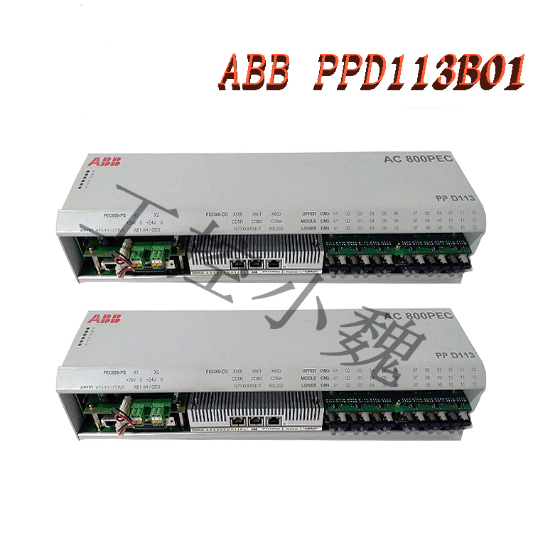
The 3BHE023584R2365 excitation control board usually has the following functions:
Excitation current control: Automatically adjust the magnitude and phase of the excitation current based on the operating status of the generator and the needs of the power grid, in order to maintain the terminal voltage and power factor of the generator within the set range.
Stability control: Monitor the operating status of the generator, suppress oscillations and instability by adjusting the excitation current, and ensure the stable operation of the generator.
Protection function: It has protection functions such as overcurrent, overvoltage, undervoltage, frequency deviation, etc. When abnormal conditions are detected, it can quickly cut off the excitation current to protect the generator and excitation system from damage.
Fault diagnosis and monitoring: By collecting and processing various sensor signals, the operating status of the excitation system is monitored in real time, and fault diagnosis information is provided to help operators quickly locate and solve faults..jpg)
Communication and interface functions: Communicate and interface with other control systems of the generator, such as automatic voltage regulators, automatic power factor controllers, etc., to achieve collaborative control and optimized operation of the entire power generation system.
The 3BHE023584R2365 excitation control board usually adopts advanced control algorithms and microprocessor technology, with high automation and intelligence characteristics. It can be customized according to different types of generators and grid requirements to meet specific operational requirements. In the power system, the 3BHE023584R2365 excitation control board is one of the key components to ensure the safe, stable, and economical operation of the generator.
All products on this website are special products, and market prices have been fluctuating,
The specific customer service quotation shall prevail, as the product is a new one and the traps are not real,
Please confirm the model, product, price, and other detailed information with customer service before placing an order. The website has been used,
New for sale, please contact the website https://www.weikunfadacai1.com/ Customer service communication.
Model recommendation:
UAD142A01
UAD142A01 3BHE012551R0001
UAD149A00-0-11 3BHE014135R0011
UAD149 3BHE014135R0011
AC800PECUAD149A0011
UAD149A00-0-11
AC800PECUAD149A0011
UAD149A0011
UAD149A0011 3BHE014135R0011
1771-WG
EASYGEN 3500XT 8440-2085
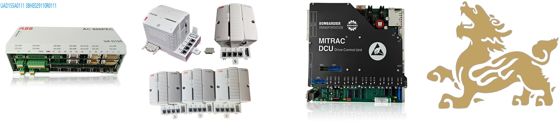
PPD113B01-10-150000
PPD113B01-10-150000 3BHE023784R1023
PPD113B03-26-100110
PPD113B03-26-100110 3BHE023584R263
PPD103B101
PPD103B101 3BHE02384R2630
PPD103B101 3BHE020455R0101
PPD103B101 3BHE020455R0101 3BHE02384R2630
PPD113-B03-23-111615 3BHE023584R2365
PPD113-B03-23-111615
PFSK108 YM322001-EH
PFSK106 YM322001-EC
PFSK111 5735175-C
More……
-300x300.jpg)
admin –
Material Order Number: 3BHE023584R2365
Internal Hardware Model: PPD113-B03-23-111615
Product Series: AC 800PEC High-Performance Power Controller, with dedicated main control board for UNITROL 6000 large synchronous generator static excitation system
Product Category: Excitation control board (core excitation regulation control unit, not a general-purpose PLC)
Origin: Original production by ABB Switzerland Power Electronics Division
II. Core Hardware Architecture
Multi-core DSP+FPGA dual-layer high-speed processing architecture: FPGA is responsible for thyristor/IGBT trigger pulses and high-speed analog sampling; DSP implements AVR voltage regulation, PSS power system stabilizer, and reactive power/power factor closed-loop algorithm.
Onboard multi-channel isolated analog input: Acquires generator PT voltage, CT stator current, excitation winding current/ Voltage
Multi-channel pulse output: Directly drives excitation rectifier bridge power devices
Dual network ports + Profibus DP, Modbus RTU communication interfaces, connecting to power plant DCS and local HMI control panels
Backplane 24VDC power supply (18~32VDC wide voltage range), total power consumption approximately 120W, built-in isolated power supply module
III. Core Functions of the Excitation System (UNITROL 6000 compatible)
Automatic Voltage Regulation (AVR)
Precise closed-loop control of generator terminal voltage, regulation accuracy ≤±0.5%, suitable for large synchronous units in hydropower, thermal power, and nuclear power
Multi-mode control switching
Automatic voltage regulation mode, manual excitation current mode, constant reactive power/constant power factor mode, test open-loop mode
Complete set of excitation limit protection logic
Overexcitation limit OEL, underexcitation limit UEL, V/Hz low frequency protection, stator current limit, instantaneous excitation overcurrent protection/ Inverse-time protection, loss-of-excitation fault detection ABB Group PSS Power System Stabilizer
Suppresses low-frequency grid oscillations, meeting domestic and international grid connection requirements.
Fault recording and event logging
Time-stamped storage of excitation disturbances, tripping, and over-limit events, supporting maintenance fault retrospective analysis.
Synchronization and start-up/shutdown sequence control
Complete excitation sequential control logic for unit grid connection, shutdown, and no-load voltage boost.
IV. Electrical and Environmental Specifications
Parameters and Technical Indicators
Power Supply: DC24V 18~32V, Isolation: 500VAC
Protection Rating: IP20 (rack mounting)
Operating Temperature: 0℃ ~ +60℃ (forced ventilation required)
Storage Temperature: -40℃ ~ +85℃
Communication: Profibus DP, Modbus RTU, Ethernet
Installation: Standard rack slot mounting, modular hot-swappable
MTBF: Greater than 30 years (ABB) (Standard Testing of Power Equipment)
V. Typical Application Scenarios
Large thermal power plants, hydropower stations, and nuclear power plants: UNITROL 6000 Static Excitation Cabinet Main Control Core
Industrial self-contained power plants and gas turbine generator excitation regulation
Synchronous synchronous condensers and large-capacity SVC static var compensator control
Marine high-power synchronous generator excitation system
Complete troubleshooting steps for ABB 3BHE023584R2365 (PPD113-B03) excitation control board
Five-level troubleshooting steps: visual inspection → power-on foundation measurement → communication diagnostics → no-load/load excitation function testing → hardware point measurement, from simple to complex, suitable for power plant on-site maintenance.
Step 1: Initial Visual Inspection After Power Off (Without powering on, the fastest way to screen for obvious damage)
Circuit Board Physical Damage
Bulging and Leaking Capacitors (Onboard DC-DC Filter Capacitors are most prone to aging);
Blackened Copper Foil, Cracked Components, Discolored Resistors;
Oxidation, Etching, and Bending/Broken Pins on the Backplane Gold Fingers;
Scorched Interface Terminals (Short-circuit marks on Pulse Output and CT/PT Analog Input Terminals).
Markings and Foreign Objects
Water Ingress, Dust, and Oil Accumulation Can Cause Hidden Short Circuits; Condensation Marks Indicate a Leakage Fault on the Circuit Board.
Jumper/DIP Switch Verification
Inconsistent DIP Switches on Spare Parts from the Same Unit: Immediate abnormality upon installation is not necessarily due to circuit board damage, but will manifest as fault symptoms.
II. Second Step: Power-Off Continuity/Resistance Measurement (Multimeter in diode and resistance modes)
1. 24V Power Supply Circuit Measurement
Backplane Power Supply Pins: DC24V Positive and Negative
Normal: Tens of kΩ input impedance in both directions;
Abnormal: Approximately 0Ω in both directions → Internal power supply short circuit, board damaged.
2. Analog Input Circuit (PT Voltage, CT Current Acquisition Channels)
Each acquisition channel must not have a direct short circuit to ground or power supply;
If a channel is conductive in both directions with extremely low resistance: Acquisition operational amplifier/voltage divider resistor burned out, sampling channel malfunction.
3. Pulse Output Channel (Trigger Thyristor Drive Terminal)
The pulse output terminal should have high resistance to ground;
If the pulse terminal is directly connected to 24V/ground: Drive optocoupler and push-pull amplifier circuit damaged, unable to output excitation trigger pulse.
4. Communication Port (Profibus / Ethernet Port)
Differential communication pins must not be short-circuited to ground; a short circuit will cause a complete communication interruption for the entire cabinet.
III. Step 3: Basic Low-Voltage Power-On Diagnosis (Only 24V backplane power is supplied; excitation power cabinet is not activated)
1. Power Indicator Status
POWER indicator light on the front of the board:
Constantly lit: Internal power module is basically normal;
Not lit/Blinking: Internal DC-DC power supply is damaged, board is stuck;
Light goes out after a few seconds of power-on: Internal overcurrent protection exists, hardware short circuit.
2. Fault Alarm Light (FAULT/ERROR)
When there is no external signal after power-on:
Brief self-test flashing followed by going out = Hardware self-test passed;
Constantly red and lit, continuously flashing = Board self-test failed, CPU/FPGA/memory chip damaged.
3. Communication Connection Test (Key Judgment Criteria)
Using ABB CMT debugging software, connect the network cable directly to the board’s Ethernet port:
If the device can be detected and the firmware version and parameters can be read normally: the main control DSP and FPGA cores are intact;
If ping fails and CMT cannot find the controller:
The network port chip is damaged;
The main control processor is frozen/damaged, and the board is unusable;
Intermittent communication: the network port or communication isolation circuit is faulty.
4. Reading Internal Fault Codes (CMT Software)
After successful power-on communication, read the fault log. Typical hardware faults indicate board damage:
HW Fault: Hardware self-test failure;
ADC Fault: Damaged multi-channel AD acquisition chip;
Pulse Driver Fault: Damaged pulse drive circuit;
Memory Error: Damaged onboard flash memory/RAM, parameters are lost and cannot be saved.
IV. Step Four: No-Load Function Test (No-Load Voltage Boost Test of Excitation System, Differentiating Between Board and Power Cabinet)
Prerequisites: Power rectifier bridge, excitation transformer, and secondary circuit are intact. Replace a confirmed intact board of the same model for comparison testing.
Excitation is activated, and a no-load voltage boost command is issued:
No voltage increase at the generator terminals, CMT displays no pulse output → Board pulse drive circuit damaged;
Voltage spikes uncontrollably, unresponsive to AVR adjustment → AD sampling channel damaged, voltage acquisition fails;
Frequent V/Hz alarms, over-excitation false alarms → Current/voltage sampling operational amplifier damaged;
Mode Switching Test (Automatic AVR/Manual Excitation Current)
Manual mode cannot adjust excitation current, no response to input: Main control adjustment algorithm or DA output channel damaged.
V. Step 5: Targeted Measurement (Precisely Locating Damaged Areas)
1. Power Module Measurement
Use a multimeter to measure the internal voltages of each circuit on the board: 5V, 3.3V, 1.8V, ±15V (analog power supply).
Any voltage missing or significantly deviating from the nominal value: The onboard isolation power module is damaged.
2. AD Analog Sampling Circuit
Apply a standard AC voltage to the PT terminal and a standard small current to the CT:
Large deviation between the CMT’s acquired value and the actual input, no reading, or erratic voltage fluctuations → AD acquisition chip/front-end operational amplifier burnout.
3. Pulse Trigger Waveform Measurement (Oscilloscope is best)
Measure the pulse output terminal under no-load boost:
No pulse waveform output: Damaged pulse drive optocoupler or FPGA pulse unit;
Distorted pulse waveform, insufficient amplitude: Damaged drive amplifier circuit, which will cause phase loss in the excitation rectifier bridge and unstable excitation.
VI. Typical Fault Phenomena Directly Identifying Circuit Board Damage (High-Frequency Field Scenario)
FAULT: Red light stays on continuously upon power-up; CMT reports HW self-test fault. The problem is resolved after replacing the spare part.
24V power-up results in a direct short circuit trip; internal power supply breakdown on the circuit board.
Complete communication interruption; no parameters can be read. Network cable/switch issues ruled out.
Voltage and current data acquisition results in garbled characters and no sampled values; secondary circuit wiring is intact.
Given a command, but no excitation trigger pulse output; power cabinet has no excitation output.
Parameters cannot be saved; all settings are cleared after power-off (onboard memory chip damaged).
Frequent random tripping and false triggering of various excitation limit protections during operation; the fault disappears after replacing the circuit board.
Frequent random tripping and false triggering of various excitation limit protections during operation. VII. Common Misconceptions (Don’t Misdiagnose If It’s Not Board Damage)
Secondary PT/CT disconnection, excitation transformer fault, thyristor breakdown → These are peripheral devices;
Poor contact in the backplane slot, unstable 24V power supply;
Incorrect CMT software parameter settings, improper PSS/limit curve settings;
Incorrect DIP switch/address code settings, leading to communication/regulation abnormalities;
Overheating of the cooling duct triggers protection, recovering after cooling.
Quick Diagnosis Summary Process
Check for burn marks or short circuit signs → If present, directly determine damage;
Power off and test for a short circuit in the 24V power supply → Short circuit = damage;
Power on and check the power supply/fault indicator, use the CMT to connect to communication and read the fault code;
If communication is possible, perform no-load voltage boost and signal acquisition tests;
Compare and replace with a working board of the same model; if the fault transfers, the original board is confirmed to be damaged.
https://www.weikunfadacai1.com/product/abb-3bhe023584r2365-2/