
Description
Many products are not yet listed online; please contact us for more information.
If the product model differs from the displayed image, the model number takes precedence. Please contact us for specific product photos; we can arrange for warehouse staff to take and verify them.
We operate 76 shared warehouses globally, so it may sometimes take a few hours to provide an accurate response; we appreciate your understanding. Rest assured, we will address your inquiries as quickly as possible.
ICP232 029.359325 Alternative Names:
ICP232 029.359325 Logic Operation Module
ICP232 029.359325 Process Control Module
DATEL Logic Operation/Input Signal Module ICP232 029.359325
I. Operating Principle
The ICP232 029.359325 utilizes the rack backplane parallel bus and an isolated CAN bus to receive excitation regulation setpoints and control commands from the SPU232.2. Simultaneously, it acquires generator terminal voltage synchronization signals and thyristor anode status feedback signals. The module features built-in independent phase-locked loop (PLL) hardware circuitry that continuously tracks the generator terminal voltage phase to resolve grid synchronization phase data. By combining this with the firing angle commands issued by the SPU, it calculates thyristor firing times in real-time and generates isolated pulse drive signals for the excitation power unit. Internally, the module is divided into four sections: signal isolation, phase-locked computation, pulse output driving, and hardware fault detection. Synchronous sampling signals undergo level conversion via high-voltage isolation circuitry to eliminate high-power interference; the hardware PLL operates independently of the SPU master controller, maintaining phase tracking even during brief communication fluctuations. Pulse output channels are equipped with independent short-circuit and overcurrent detection circuits, with pulse-width verification performed on every firing pulse. If pulse loss, pulse distortion, or abnormal power circuit feedback is detected, pulse output is immediately inhibited, and fault codes along with phase snapshots are reported to the SPU232.2 processor via the backplane bus. The module employs a periodic synchronous scanning mechanism synchronized with the SPU232.2 clock, ensuring nanosecond-level alignment of control timing. It features an onboard hardware watchdog that automatically cuts off pulse output if the local computation program malfunctions, preventing accidental triggering that could lead to loss of excitation control.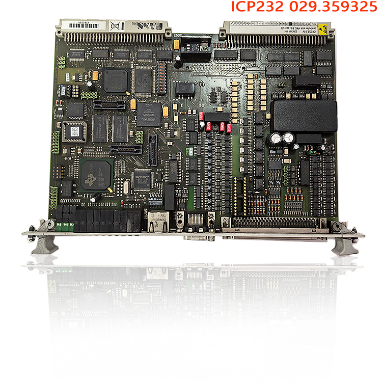
II. Product Functions
Excitation pulse generation and power interface conversion: Receives firing angle commands calculated by the SPU232.2, performs phase-locked synchronization, and outputs high-power isolated firing pulses to directly drive the thyristors in the excitation power cabinet; it acts as the bridge between the excitation main control board and the power rectifier bridge. The SPU handles the AVR closed-loop algorithm, while the ICP232 029.359325 manages precise pulse timing output; the two work collaboratively.
Synchronous voltage acquisition and phase monitoring: Acquires synchronous voltage signals from the generator terminal (PT), performs real-time phase and frequency monitoring, and provides the synchronization reference for grid connection, field suppression, and field flashing; detects conditions such as frequency anomalies, loss of synchronism, and synchronization signal disconnection, reporting faults promptly.
Power-side status feedback and preliminary protection: Acquires thyristor operating status and power circuit fault signals for preliminary assessment; immediately blocks pulses upon detecting short circuits or pulse circuit disconnections, providing a first line of hardware protection to prevent faults from propagating to the SPU main controller.
Auxiliary processing of excitation system interlocking logic: Handles local hardware interlocking for field flashing, field suppression, and pulse switching, coordinating with the SPU to execute excitation activation/deactivation logic; executes preset safety actions—such as blocking firing pulses—in the event of main control board communication failures to ensure unit safety.
Fault data acquisition and event snapshot upload: Records event information such as pulse faults, synchronization signal anomalies, and channel overloads; uploads this data—timestamped—to the SPU processor for retrieval by the supervisory monitoring system, facilitating root-cause analysis of excitation faults.
III. Product Advantages
Hardware-based phase-locking for superior control reliability: The phase-locking function is implemented in hardware, consuming no SPU main control computing resources. Consequently, trigger pulse phase accuracy remains unaffected even during brief periods of high main control load, making it ideal for generator grid-connection and precise reactive power regulation.
High/low-voltage isolation and layered design: Independent isolation components are used for both synchronization signals and pulse drive channels. This electrically isolates the high-voltage side of the excitation power cabinet from the low-voltage control board, blocking electromagnetic interference caused by high-power thyristor switching and reducing the risk of damage to the main control board.
Layered fault protection mechanism: Features hardware-level pulse blocking capabilities, allowing for rapid pulse shutdown in response to software or communication faults—unlike standard boards that rely solely on software protection. Fault response is significantly faster than main control software protection, minimizing the risk of uncontrolled excitation.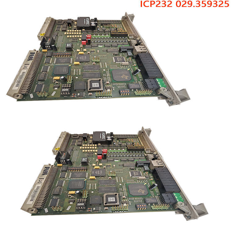
Hardware compatibility within the series for easy spare part replacement: As a native component of the Semipol D3.1 series, its backplane interfaces and bus protocols are fully compatible with the SPU232.2, PIB101, and DIZ232. Retrofitting excitation systems on older units requires no changes to cabinet wiring; only firmware version verification is needed.
Industrial-grade, corrosion-resistant hardware for wide temperature ranges: The PCB features a conformal coating, enabling reliable operation in the high-temperature, humid, dusty, and high-vibration environments typical of power plants. Components meet the requirements for continuous 24/7 power station operation and offer a long Mean Time Between Failures (MTBF).
Independent pulse channel diagnostics: Each pulse output channel supports real-time monitoring of pulse width and amplitude. This enables the pinpointing of faults in individual pulse circuits, allowing maintenance personnel to quickly identify issues with power cabinets or board channels and reducing downtime associated with troubleshooting.
4. Operating Procedures (Installation, Power-up & Commissioning, Spare Part Replacement, O&M Prohibitions)
1. Pre-installation Checks
Power down the entire unit, ensure all AC and DC excitation power supplies are disconnected, and wait for the power cabinet capacitors to fully discharge; use a multimeter to verify there is no residual voltage at the backplane power terminals. Inspect the ICP232 029.359325 board: ensure the PCB shows no signs of burning, the gold fingers are free of oxidation, and the pulse output terminals are secure; verify the board model matches the original spare part; clean dust from the rack slot and check the backplane pins for bending or deformation. Confirm that the associated SPU232.2, PIB101, and DIZ232 modules are in place, and verify the wiring for the backplane bus, synchronization voltage input, and pulse output cables against the schematics. Hot-swapping this module is strictly prohibited.
2. Rack Installation
Slide the board smoothly into the slot along the cabinet guide rails; apply even pressure to the front panel to ensure the gold fingers make full contact with the backplane, then tighten the panel mounting screws to prevent poor contact caused by unit vibration. Connect the synchronization voltage signal lines, pulse output cables, and backplane bus in sequence; use single-point grounding for the synchronization signal shielded cables—multi-point grounding is prohibited to avoid ground potential interference. Check the DIP switch settings on the back of the board to ensure they match the original system bus address.3. Power-on Commissioning Steps
1) Double-check all wiring to ensure the synchronization voltage input range and pulse output connections correspond correctly to the thyristor circuits in the power cabinet; 2) Apply auxiliary power to the cabinet, observe that the board’s power indicator remains steadily lit, and wait for board initialization; the RUN light should flash steadily upon successful initialization, whereas the FAULT light indicates a self-test failure (requiring immediate power-off to inspect wiring and backplane connections); 3) Use the supplied commissioning software to connect to the SPU232.2 via the CAN bus, read the ICP232 029.359325 board’s firmware version and hardware ID, and verify that the firmware version matches the unit’s excitation program; 4) No-load static test: With the unit not yet excited, activate the system to monitor synchronization voltage acquisition, phase, and frequency data, ensuring there are no “loss of synchronization signal” alarms; issue firing angle commands and monitor pulse output channels to verify correct pulse timing and width; 5) No-load excitation commissioning: Initiate excitation and slowly ramp up the terminal voltage; observe that the pulse phase changes stably in tracking with the terminal voltage, with no alarms for pulse loss or sudden jumps; simulate loss-of-synchronization and synchronization line-breakage faults to verify that the module can rapidly block pulses and report the fault; 6) On-load integrated commissioning: Connect the unit to the grid and apply load; verify pulse regulation response across different reactive load ranges, ensuring stable pulse output and no abnormal alarms; upon completion, export fault event records and back up the complete set of excitation parameters.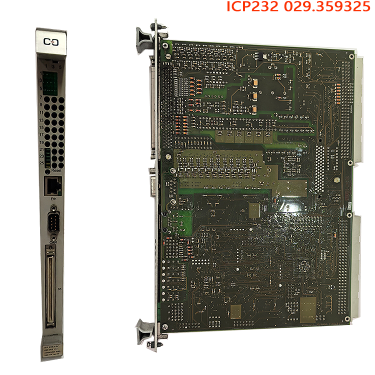
4. Routine O&M and Spare Parts Replacement
During routine inspections, check the RUN and FAULT indicators on the board; periodically monitor the status of ICP232 029.359325 pulse channels and synchronization signals, as well as historical alarm codes, via the supervisory control system. When the module detects a fault, initiate the unit shutdown procedure, disconnect the main power supply to the excitation cabinet, and wait for the power capacitors to fully discharge. Then, remove the faulty board, replace it with a spare following the installation steps, verify the firmware version and synchronization wiring, and complete the no-load verification before placing the unit back into operation.
5. Safety Prohibitions
Do not insert or remove the ICP232 029.359325 board while the power is on; do not touch the synchronization input terminals or pulse output terminals until discharge is complete; do not arbitrarily modify pulse output parameters or phase-lock thresholds; do not perform online firmware updates while the unit is under high-power load; and do not short-circuit pulse output channels for power-on testing.
Related product recommendations:
RET630 1KHL160003R0001H
3BHB030845R0101 ABB
3BHB050206R0100 ABB
3BHE055094R0002 ABB
3BHB030310R0001 ABB
GBU72 3BHE055094R0002
GBU72 3BHB030310R0001
S-093H 3BHB030478R0009
3BHB009884R0021 S-073N
3BHB009885R0052 S-097H
3BHB009885R0013 S-093M
ABB S-093H 3BHB030478R0309
ABB S-093S 3BHB030475R0009
S-093S 3BHB030475R0009
S-073N 3BHB009884R5211
S-073N 3BHB009884R0021 35SHY3545L0014
S-053M 3BHB012897R0003
S-073N 3BHB009884R0021 35SHY3545L0014
S-073N ABB 3BHB009884R0021
S-097H 3BHB009885R0052
S-093H 3BHB030478R0309
More……

Reviews
There are no reviews yet.