
Description
All products on this site are specialized items subject to fluctuating market prices.
Please rely on the quote provided by customer service, as the listed prices are not definitive.
Before placing an order, please confirm details such as the model, product specifications, and price with customer service.
Please contact customer service for inquiries regarding these products.
SPU232.1-CAN Alternative Names:
Logic Operation Module SPU232.1-CAN
SPU232.1-CAN Embedded Control Unit
CAN System Single-Processor Board SPU232.1-CAN
I. Operating Principle
The SPU232.1-CAN is an embedded real-time processor board based on an independent single-core architecture. Serving as the local computational core for the entire excitation regulation system, it utilizes the backplane bus and multiple isolated CAN buses to facilitate closed-loop signal interaction. Analog signals—such as generator voltage, current, and rotational speed—are first sent to the matching PIB101 measurement board for signal conditioning before being transmitted to the SPU232.1-CAN. Digital status signals are acquired by the DIZ232 digital input board and transmitted to the processor unit via the backplane. The onboard core performs analog-to-digital conversion and noise filtering on the acquired signals, then executes periodic calculations using built-in excitation PID regulation algorithms, synchronization logic, and limit protection models. Upon completion of calculations, it outputs pulse setpoints and switching control commands to the pulse generation module to trigger the excitation thyristors. The board features built-in hardware-level self-diagnostic circuitry that synchronously verifies register status, bus messages, and supply voltage during every scan cycle. In the event of computational anomalies or communication packet loss, a local fault flag is immediately triggered and reported to the upper-level monitoring system via the CAN bus, enabling real-time fault identification. A multi-channel isolated CAN2.0B bus serves as the data exchange channel; it employs a magnetic isolation scheme to block interference from the high-voltage side, ensuring deterministic communication in high-electromagnetic-noise environments and enabling distributed data exchange between the processor, I/O boards, and the supervisory control system. The system utilizes a fixed-cycle scanning mechanism that prioritizes the execution of excitation regulation and protection logic—deferring the processing of non-critical monitoring data—to meet the strict real-time requirements of generator excitation control.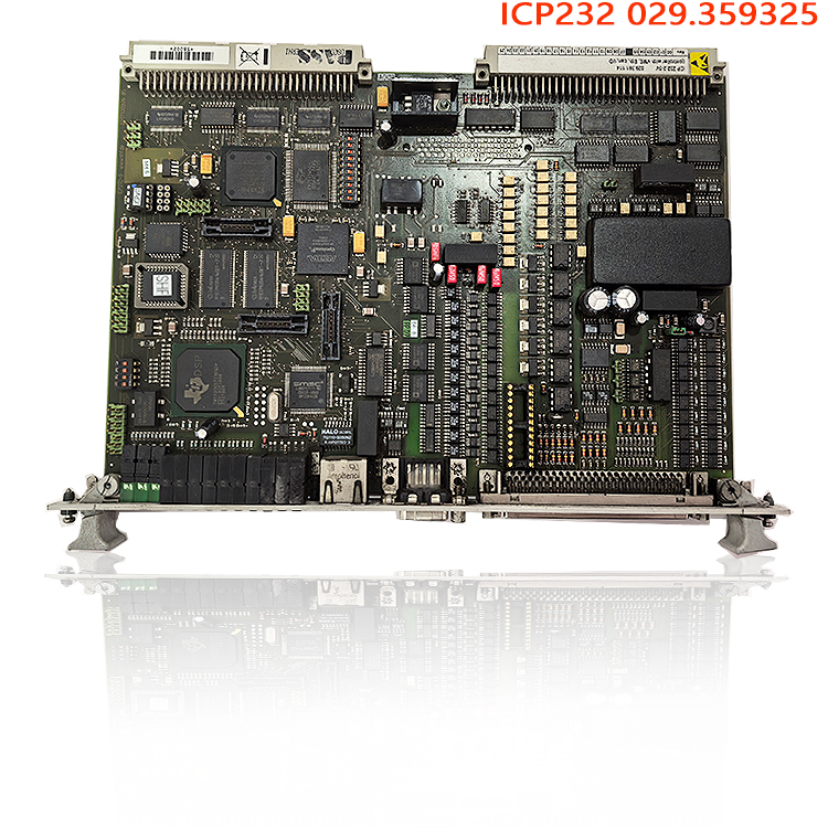
II. Product Functions
Core Excitation System Control: Acting as the “brain” of the Semipol D3.1 Automatic Voltage Regulator (AVR), it executes core control algorithms—including AVR, reactive power regulation, stator/rotor current limiting, and under-excitation/over-excitation limiting—and issues trigger commands to maintain stable generator terminal voltage.
Logic Interlocking and Protection: Performs interlocking checks for various discrete signals (such as circuit breaker status, excitation switching interlocks, and system fault trip logic); upon detecting anomalies in the excitation circuit, it rapidly executes limiting or tripping protection actions to prevent the escalation of faults on the excitation side.
Distributed Bus Data Management: Manages the CAN bus network within the excitation cabinet, collecting real-time data from I/O and measurement boards and uploading operating parameters, event logs, and fault codes to the supervisory control system; simultaneously receives, parses, and locally executes control commands issued by the supervisory system.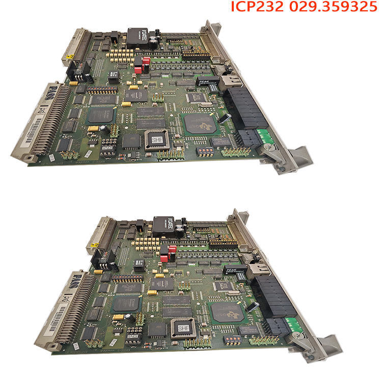
Local Status Diagnosis and Event Logging: Continuously monitors the operational status of the board’s internal power supply, memory, bus links, and chips, recording system snapshots at the moment of a fault to facilitate subsequent root-cause analysis. System-wide Coordinated Control: Works in concert with the ICP232 control board, PIB101 measurement board, and DIZ232 input board to form a complete excitation control hardware system. The single-processor architecture simplifies the hardware hierarchy of the excitation control unit, making it suitable for excitation system retrofits in thermal, hydro, and gas turbine generator units.
III. Product Advantages
Real-time Control Tailored for Energy Applications: Specifically developed for generator excitation regulation, featuring a fixed scan cycle and highly deterministic control timing. Unlike general-purpose PLCs, it incorporates built-in excitation-specific control models—eliminating the need for extensive custom programming—and is optimized for closed-loop generator voltage regulation.
Robust Anti-interference Hardware Design: Features conformal coating on PCBs, independent magnetic isolation for onboard CAN channels, and filtering circuits on backplane signal lines. It withstands strong electromagnetic interference from high-voltage switchgear and variable frequency drives (VFDs), while remaining resilient against the harsh cabinet environments (humidity, vibration, and dust) typical of power plants.
Streamlined Architecture and Maintenance-friendly Design: Employs a single-processor architecture with a simplified hardware structure and centralized fault points. Compatible with original ALSTOM backplanes, it allows for backward-compatible replacement of the SPU232.1-CAN unit; this ensures high compatibility for retrofitting excitation systems on older units without requiring extensive rewiring of the cabinets.
Comprehensive Built-in Self-diagnosis System: Utilizes dual hardware and software diagnostics to output real-time fault codes and support remote retrieval of fault snapshots. This significantly reduces on-site troubleshooting time and minimizes unit downtime for maintenance.
Long-term Stable Operation Capability: Designed for a wide industrial temperature range and supports continuous 24/7 operation. Component selection meets the rigorous demands of long-term service in power plants, making it a mainstream replacement option for existing Alstom/Converteam excitation systems. Standardized bus expansion capability: Features multiple independent CAN2.0B communication interfaces with communication speeds up to 1 Mbps; supports flexible expansion of I/O and measurement modules, as well as data synchronization across multiple excitation cabinets.
IV. Operating Procedures (Installation, Power-up, Commissioning, and Replacement)
1. Pre-installation Checks
Ensure the excitation system’s main power supply is completely disconnected and use a multimeter to verify there is no residual voltage at the backplane power terminals. Inspect the SPU232.1-CAN board for physical defects: ensure the PCB is free of corrosion and burn marks, the gold fingers show no signs of oxidation or damage, and the interface terminals are intact. Verify the board model and serial number against the original spare part specifications. Clean dust from the rack backplane slots and ensure the backplane is free of deformation or bent pins.
2. Rack Installation Procedure
Slide the board smoothly into the slot along the rack guide rails and apply even pressure to the front panel to ensure full contact between the gold fingers and the backplane. Tighten the panel mounting screws to prevent the board from loosening due to vibration. Connect the CAN bus communication cables sequentially, ensuring the bus shield is grounded at only one end to avoid interference caused by multi-point grounding. After wiring, verify the CAN bus address DIP switch settings to ensure they match the original system configuration.
Note: This board does not support hot-swapping; the entire unit must be powered down before insertion or removal. Inserting or removing the board while powered on will result in immediate damage to the processor and backplane circuitry.3. Power-on Commissioning Steps
1) Confirm that all associated I/O boards and measurement boards are correctly installed and wired, and verify that the supply voltage is within the rated range; 2) Apply auxiliary power to the cabinet first and observe the status indicators on the SPU232.1-CAN board; a steady power indicator signifies normal power supply; wait for initialization—a steadily flashing RUN indicator indicates the processor has started correctly, while an illuminated FAULT indicator signifies a self-test failure (in which case, disconnect power to check the backplane and DIP switch settings); 3) Use the associated commissioning software to connect to the board via the CAN bus; read the firmware version and hardware ID, and verify that the program version matches the unit’s excitation parameters; 4) Read the unit’s original excitation parameters online and confirm that voltage regulation and various limit/protection parameters match the unit’s settings; if parameters are incorrect, download the matching program online; 5) No-load test: With the unit at no-load, activate the excitation system; observe the response of the terminal voltage regulation and check for bus data stability, ensuring there are no communication errors or abnormal alarms; 6) On-load integrated testing: Gradually increase the unit load to verify reactive power regulation and the operation logic of excitation limiting functions, and confirm the accuracy of protection threshold operations; 7) Upon completion of commissioning, save a parameter backup, export event logs, and archive the parameter records.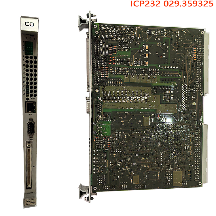
4. Routine Maintenance and Spare Part Replacement
During routine inspections, observe the status of the board’s RUN and FAULT indicators, periodically review diagnostic information uploaded to the supervisory system, and record alarm codes; if a board fault is detected, execute the shutdown procedure, disconnect the main power to the excitation cabinet, and wait for the capacitors to discharge completely before removing the faulty board; replace the board following the installation steps described above, re-download the unit’s excitation parameters, and place the system back into operation after completing no-load verification.5. Safety Precautions
Do not insert or remove circuit boards while the power is on; do not touch backplane terminals without first discharging residual energy; do not arbitrarily modify excitation protection settings; do not perform program downloads in environments with strong electromagnetic interference.
Self-Check & Verification
Accuracy Verification: Clearly identify the SPU232.1-CAN as part of the Semipol D3.1 excitation regulator—rather than a general-purpose DCS board—thereby correcting common market misconceptions that label it as a rail transit board or a standard I/O module. Clarify the associated board combination (ICP232, PIB101, DIZ232), ensuring the technical explanation aligns with generator AVR excitation closed-loop principles and reflects real-world power plant spare part applications.
Uniqueness Verification: Move beyond generic, template-style descriptions (e.g., “signal acquisition – calculation – output”) by incorporating details on scan priorities, CAN magnetic isolation, parameter backup, commissioning procedures for no-load/loaded unit states, and key points regarding spare part compatibility and replacement. This approach is tailored for B2B industrial spare part listings and benefits search engine rankings.
Structural Completeness: Features a comprehensive four-module structure covering principles, functions, advantages, and operating methods. Presented as plain text (no images or tables), it is ready for immediate copy-and-paste listing; the language balances technical professionalism with effective product copywriting.
Related product recommendations:
RET630 1KHL160003R0001H
3BHB030845R0101 ABB
3BHB050206R0100 ABB
3BHE055094R0002 ABB
3BHB030310R0001 ABB
GBU72 3BHE055094R0002
GBU72 3BHB030310R0001
S-093H 3BHB030478R0009
3BHB009884R0021 S-073N
3BHB009885R0052 S-097H
3BHB009885R0013 S-093M
ABB S-093H 3BHB030478R0309
ABB S-093S 3BHB030475R0009
S-093S 3BHB030475R0009
S-073N 3BHB009884R5211
S-073N 3BHB009884R0021 35SHY3545L0014
S-053M 3BHB012897R0003
S-073N 3BHB009884R0021 35SHY3545L0014
S-073N ABB 3BHB009884R0021
S-097H 3BHB009885R0052
S-093H 3BHB030478R0309
More……

Reviews
There are no reviews yet.