
Description
Many products are not yet listed. Please contact us for more information.
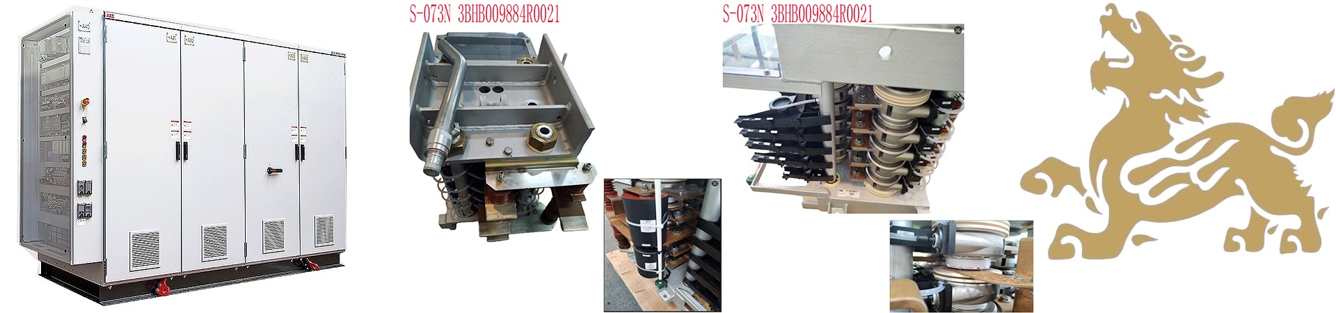
If the product model differs from the displayed image, the model number shall prevail. Please contact us for specific product images, and we will arrange to take photos in our warehouse for confirmation.
We have 76 shared warehouses worldwide, so it may sometimes take several hours to accurately return the information to you. We appreciate your understanding. Of course, we will respond to your inquiries as soon as possible.
Marine differential current relays (ANSI standard number 87G) are the main protection for marine synchronous generators, specifically designed to protect against internal short circuits in the generator stator. They are mandatory for marine generator sets of 1400kVA and above (classification society specifications). Ordinary current and reverse power protection can only protect external generator circuits and cannot identify phase-to-phase/turn-to-turn short circuits within the windings. The differential relay is the only core device that quickly clears internal faults.
I. Two Main Protection Characteristics of Marine Differential Relays (Mainstream Digital Type)
1. Ratio-Restricted Differential (Main Protection)
Distinguishing between internal and external faults: In the event of a large external short circuit, the braking current suppresses protection to prevent false tripping; it trips sensitively for internal faults.
Standard setting range: Starting current 0.2~0.3Ie, braking slope 0.3~0.5, inflection point current 0.5~1Ie (generator rated current).
2. Differential Instantaneous Overcurrent Protection (Rapid Clearance for Severe Short Circuits): In the event of a severe internal metallic short circuit, tripping instantaneously within 50ms without braking logic, preventing winding burnout and insulation breakdown.
II. Additional Supporting Functions (Standard for Marine Use)
Differential Current Over-Limit Alarm: If the differential current exceeds the alarm value but has not reached the tripping value, an audible and visual alarm is triggered to proactively check for potential CT and wiring hazards.
CT Disconnection Interlock: Monitors for CT disconnection/secondary open circuits to prevent false tripping due to unilateral CT failure.
Three-Phase Independent Phase Measurement: Individual alarm and tripping for single-phase faults.
III. Typical Marine Application Scenarios
Main Generator Set Protection (Most Commonly Used): Diesel synchronous generators, high-power shaft-driven generators;
High-Power Electric Propulsion Motor Differential Protection (Special Electric Propulsion Ships);
Protection Scope: Generator stator three-phase windings, neutral point lead-out line, and cable from the generator terminals to the inside of the circuit breaker.
IV. Common Faults and Troubleshooting (Ship Maintenance)
1. Differential Protection Unexplained Alarm/False Trip
CT Polarity Reversal (Most Common): Incorrect connection of the same-name terminals on both CTs, resulting in large differential current during normal operation;
CT Ratio Mismatch, CT Aging and Saturation;
Loose Secondary Wiring, Grounding, Insulation Damage;
Ship Synchronization Impact, Excessive Harmonics.
2. Failure to Operate During Internal Short Circuit
Operating Current Setting Value Too High;
CT Secondary Circuit Open Circuit, Fuse Blown;
Trip Circuit Open Circuit, Demagnetizing Coil Failed.
3. CT Open Circuit Alarm
CT Secondary Cable Damaged, Terminal Loose;
Internal Open Circuit of Current Transformer, Never Disconnect CT Secondary Circuit Under Live Voltage (High Voltage Danger).
V. Ship Installation and Inspection Standards
CTs must be arranged in pairs, with the neutral point corresponding one-to-one with the engine terminal CT, and polarity strictly verified;
Shielded cables should be used in the secondary circuit, with single-end grounding to reduce electromagnetic interference in the engine room;
Mandatory tests for annual ship inspection/dock repair:
Static differential current test (unbalanced current measurement under no-load);
Simulated fault transmission test within/outside the zone;
CT disconnection function verification;
The output circuit must simultaneously disconnect the circuit breaker and excitation; tripping only the switch will cause a continuous short circuit and burn out the windings.
VI. Differences from ordinary overcurrent relays
Protection range: Differential relays only protect the generator internally; overcurrent relays protect external lines and busbar short circuits;
Operating speed: Differential relays operate instantaneously in < 40ms; overcurrent relays have inverse time delay;
Selectivity: Differential relays do not operate on external faults, only on internal faults, and will not mistakenly disconnect normal units.
VII. Complete Working Principle of Marine Differential Current Relay
1. Basic Prerequisite: Paired Installation of Current Transformers (CTs)
Taking a marine synchronous generator differential protection (87G) as an example:
One set of three-phase current transformers (CTs) of the same model, transformation ratio, and characteristics are installed at both the generator terminals and the generator neutral point.
The secondary windings of the two CTs are connected in reverse, with two wires leading out from the middle to connect to the differential current circuit of the differential relay.
Simply put: For the same phase winding, one end enters the CT, and the other end exits the CT, with the current flowing into the relay in reverse.
2. Core Law: Kirchhoff’s Current Law
Ideally, the current flowing through the generator stator winding is equal to the current flowing out of the winding.
The two sets of CTs induce currents of equal magnitude but opposite direction on their secondary windings, which cancel each other out.
The relay detects the difference between the two currents; this difference is the differential current Id.
3. Operating Logic for Three Operating Conditions
(1) Normal Load, External Short Circuit (External Fault)
Current Path: Grid Load / External Short Circuit Point → Generator Terminal → Stator Winding → Generator Neutral Point.
Temperature of Generator Terminal CT Secondary Current = Temporary Current of Neutral Point CT Secondary Current
The two currents cancel each other out, differential current Id≈0
The relay does not operate, will not trip, perfectly avoiding accidental shutdown due to external faults.
(2) Generator Stator Internal Short Circuit (Internal Fault, Protection Operation)
When there is a phase-to-phase short circuit, turn-to-turn short circuit, or ground short circuit in the stator winding, the short circuit point is within the protection zone surrounded by two sets of CTs:
A portion of the current no longer flows through the neutral point CT, but is directly discharged from the short circuit point.
At this time: Generator Terminal CT Current ≠ Neutral Point CT Current, the currents cannot be completely canceled out, resulting in a significant differential current Id. When the differential current exceeds the relay’s set operating value, the protection immediately operates:
It trips the generator’s main air circuit breaker (ACB), disconnecting it from the ship’s electrical grid;
It cuts off the excitation circuit, quickly demagnetizes, eliminates the short-circuit power supply, and prevents the generator stator from burning out.
(3). Special Operating Conditions of CT Secondary Circuit Disconnection
An open circuit in the CT secondary circuit will generate high voltage, and simultaneously, there will be no current on one side, resulting in a false differential current.
Modern marine differential relays have a built-in CT disconnection interlocking function: when no current is detected in a single circuit, an alarm is issued, and the trip is simultaneously interlocked to prevent normal units from mistakenly disconnecting from the grid. (4) Mainstream Marine Application: Ratio-Resistant Differential Protection Principle (Solving CT Saturation Malfunction)
The short-circuit current in the ship’s engine room is extremely high. During a major external fault, the CT is prone to saturation, leading to an imbalance of current between the two CTs. This can cause false differential currents and result in false tripping. Therefore, all ships use ratio-resistant differential protection:
Resistant Current: The maximum current output from both CTs is used. The larger the external fault current, the larger the restrictive current.
The operating current threshold increases synchronously with the restrictive current.
External Short Circuit: A large restrictive current raises the operating threshold, preventing false differential currents from reaching the operating value and ensuring reliable operation.
Internal Short Circuit: A large current difference between the two sides results in a small restrictive current, easily exceeding the operating value and causing instantaneous tripping.
(5) Differential Instantaneous Auxiliary Protection Principle (Heavy-Duty Short Circuit Extreme-Speed Protection)
When a severe metallic short circuit occurs inside the generator, the differential current is extremely high. The ratio-resistance logic is directly bypassed, and the differential instantaneous tripping element operates instantaneously (≤50ms), quickly cutting off the fault and preventing stator insulation burnout and core damage.
Recommended related products:
ALSTOM MAE 00-06
ABB CT-MFE-1SVR550029R8100
TAIYO ELECTRIC AS-71-2
STAMFORD AVK QPF-V5
SIEMENS A541432
REXROTH MECMAN 3460565500
PR ELECTRONICS 2229
NORIS SAR010-1G
AVK COSIMAT N
WIJDEVEN PTLS 12D400C2
WESTERSTRAND 500500-SP
VODEC INDUSTRIAL VA300-PSU
VODAVI LDK-300 PSU
More……

Reviews
There are no reviews yet.