
Description
Many products have not yet been listed online; please contact us for more information.
If there is a discrepancy between the product model and the displayed image, the model number takes precedence. Please contact us for specific product photos; we can arrange for warehouse staff to take and provide confirmation images.
We operate 76 shared warehouses globally; consequently, it may sometimes take a few hours to provide you with an accurate response. We appreciate your understanding. Rest assured, we will address your inquiries as quickly as possible.
IS420UCSCH2A-C-V0.1-A Other names:
Output module IS420UCSCH2A-C-V0.1-A
IS420UCSCH2A-C-V0.1-A controller module
Editable controller IS420UCSCH2A-C-V0.1-A
Product Overview
The GE IS420UCSCH2A-C-V0.1-A is a high-performance Universal Controller Single (UCS) module within the Speedtronic Mark VIe distributed control system from GE (now GE Vernova). Serving as the “computational brain” of the control rack, it executes turbine control logic, manages high-speed I/O communication, and coordinates unit protection and safety interlocking functions.
The module features a 1.6 GHz AMD G-Series dual-core processor running the QNX Neutrino real-time operating system, equipped with 2 GB of DDR3 RAM and 40 GB of SSD storage. It communicates with distributed I/O modules via GE’s proprietary IONet real-time Ethernet and offers scalable support for mainstream industrial protocols such as PROFINET. With its deterministic real-time control capabilities, flexible redundancy architecture, and SIL 2/3 functional safety certification, the IS420UCSCH2A is widely used in gas turbines, steam turbines, compressors, and critical industrial process control applications.
I. Operating Principle
The operating principle of the IS420UCSCH2A can be summarized as a cycle comprising four stages: real-time data acquisition, deterministic computation, closed-loop output, and safety protection.
1. Field Signal Acquisition: Analog and discrete signals—such as temperature, pressure, rotational speed, vibration, and valve position—are first input into the Mark VIe system’s distributed I/O modules. After signal conditioning and analog-to-digital conversion, the data is transmitted to the controller via the IONet real-time Ethernet. IONet utilizes GE’s proprietary deterministic communication protocol, achieving refresh cycles as fast as under 5 ms, thereby ensuring that control data is delivered within strict time windows.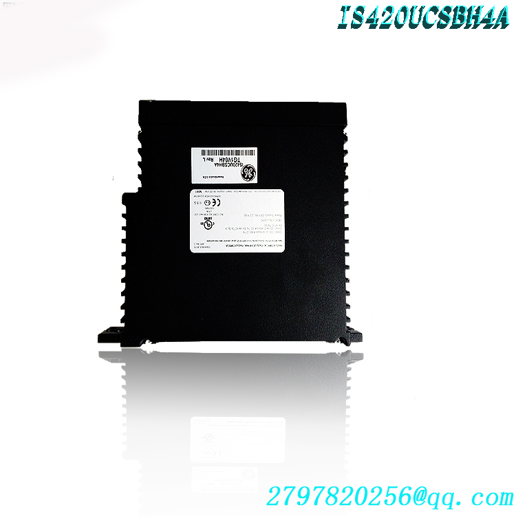
2. Real-Time Control Computation: The controller executes user-defined control strategies on the QNX Neutrino real-time multitasking operating system. A dual-core processor distributes tasks in parallel—separating “control logic computation” from “data processing, communication, and diagnostics”—to ensure that critical algorithms (such as speed regulation, fuel/steam valve positioning, and load distribution) are executed deterministically within fixed scan cycles. “Determinism” implies that the control loop’s response time remains predictable and repeatable regardless of the volume of simultaneous communication and diagnostic tasks; this is crucial for millisecond-level safety functions like overspeed protection and anti-surge control.
3. Closed-Loop Control Output: Computation results are transmitted via IONet to the corresponding I/O output modules. These modules drive actuators—such as electro-hydraulic servo valves, fuel control valves, and trip solenoid valves—to form a complete closed-loop control circuit that adjusts the unit’s operating status in real time.
4. Fault Diagnosis and Protection: The controller features built-in self-diagnosis and status monitoring capabilities, continuously monitoring the power supply, CPU, memory, communication links, and I/O channels. Upon detecting limit violations or faults, the system immediately triggers alarms, load reduction, or emergency shutdowns (trips) based on preset logic, thereby safeguarding the unit and personnel before an incident can escalate. In a redundant configuration, memory is synchronized between the primary and backup controllers, ensuring virtually seamless failover.
II. Key Technical Specifications
Specifications
Product Model
IS420UCSCH2A-C-V0.1-A
Manufacturer
GE / GE Vernova
Product Type
Universal Controller Module (UCS), Dual-core CPU Controller
System Compatibility
GE Speedtronic Mark VIe / Mark VIeS
1.6 GHz AMD G-Series dual-core microprocessor
Memory
2 GB DDR3 (supports ECC error correction)
Storage
40 GB SSD (Solid State Drive)
Operating System
QNX Neutrino 6.5 / 7.1 Real-Time Operating System
Supply Voltage
18–36 VDC (nominal 24 VDC)
Power Consumption
Typical ~12 W, Maximum ~31 W
Communication Interfaces
IONet, 6 Ethernet (RJ-45) ports, 1 USB 2.0 port
Supported Protocols
IONet, PROFINET, Modbus, EtherNet/IP, etc.
Redundancy
Supports Simplex, Duplex, and Triple Modular Redundancy (TMR) configurations
Functional Safety
Compliant with IEC 61508; capable of SIL 2 / SIL 3 Ratings
Operating Temperature
Industrial-grade wide-temperature design (refer to the model nameplate and official GE manuals for specific details)
Front Panel Indicators
LEDs for Power, Boot, Online, Flash, DC, Diag, Link/Act, etc.
III. Product Advantages
1. High-performance dual-core architecture with strong real-time determinism: Compared to traditional single-core controllers, the 1.6 GHz dual-core architecture enables parallel processing of control calculations and communication diagnostics. This ensures rapid, stable control cycles while effortlessly handling rapid load fluctuations and complex control algorithms.
2. Flexible redundancy configuration capabilities: The module supports simplex, dual, and even Triple Modular Redundancy (TMR) architectures. Users can flexibly select configurations based on unit safety requirements and budgets—employing TMR (two-out-of-three voting) for critical main loops to eliminate single points of failure, while using simplex configurations for auxiliary systems to control costs, thereby striking a balance between reliability and economy.
3. Highly reliable industrial-grade design: Features a fanless cooling design to minimize mechanical failure points. Combined with G3 anti-corrosion coating and wide-temperature adaptability, it ensures stable, long-term operation in harsh industrial environments characterized by high temperatures, high humidity, and strong vibrations.
4. Open and extensive communication capabilities: A multi-port design allows for the physical isolation of different network segments—such as the control network (IONet), HMI, remote diagnostics, excitation communication, and plant-level DCS. This ensures the real-time reliability of control data while meeting the demands of the modern Industrial Internet of Things (IIoT) and data integration.
5. Comprehensive software and diagnostic support: Compatible with GE ControlST/ToolboxST engineering software, supporting offline simulation, online configuration, remote diagnostics, and encrypted firmware upgrades. Parameter modifications can be performed without physical jumpers or DIP switches, significantly reducing commissioning and maintenance time.6. Functional Safety Certification: Certified for SIL 2/3 functional safety (compliant with IEC 61508), the unit can directly execute safety instrumented functions such as overspeed protection and emergency shutdown, providing systematic safety assurance for personnel, equipment, and the environment.
IV. Roles in Various Application Industries
1. Power Generation Industry: The IS420UCSCH2A serves as the core control unit for gas turbines, steam turbines, and combined-cycle units. It manages unit start-stop sequencing, speed and load regulation, fuel/steam valve control, exhaust temperature regulation, and overspeed protection, directly determining the generator unit’s operational efficiency, availability, and safety level. For power plants, this controller is a critical component for ensuring stable grid connection, optimizing fuel efficiency, and minimizing unplanned downtime.
2. Oil & Gas Industry: In applications such as long-distance pipeline compressor stations, offshore platforms, and wellhead separation and boosting, the module handles compressor unit control and anti-surge protection. It monitors inlet/outlet pressure, temperature, and flow in real-time, ensuring the unit operates safely within its defined operating envelope. Its explosion-proof capabilities and wide operating temperature range make it suitable for the harsh environments of remote, unmanned stations.
3. Chemical and Petrochemical Industries: Used in process control and safety interlock systems, the module handles complex process optimization logic and emergency shutdown (ESD) interlocks. It triggers timely actions in response to anomalies in critical parameters—such as temperature, pressure, and liquid level—thereby ensuring continuous production and plant safety.
4. Metallurgy, Water Utilities, and Distributed Energy: Widely utilized in high-precision metallurgical process control, water treatment automation, wind power control, and plant-level DCS and SCADA data acquisition and monitoring systems. Acting as a field control node within a distributed control architecture, it enables decentralized control combined with centralized management. 5. Marine and Maritime Applications: Backed by relevant classification society certifications and a high-reliability design, this controller series is suitable for marine electric propulsion and power plant control systems, ensuring the safe operation of power systems in maritime environments characterized by vibration, motion (pitch/roll), and salt spray.
V. Operation, Installation, and Commissioning
1. Pre-installation Preparation
Ensure the operating environment temperature and humidity meet specifications; the installation location must be well-ventilated and free from corrosive gases and severe vibration.
Wear an anti-static wrist strap (ESD protection); the module contains static-sensitive components, so avoid direct contact with circuit boards and metal contacts.
Verify that the power supply is 24 VDC (range: 18–36 VDC) and includes overvoltage, overcurrent, and short-circuit protection.
Personnel must have received professional training on the GE Speedtronic system and be familiar with the relevant technical manuals.
2. Hardware Installation
Disconnect power to the rack and smoothly insert the module along the guide rails into the designated controller slot of the Mark VIe control rack.
Align the module with the backplane connector and press firmly with even force to ensure full pin engagement; then, tighten the mounting screws to the specified torque.
Leave sufficient clearance around the module for heat dissipation and cable routing; connect Ethernet and IONet cables to their respective ports according to network segment labels.
3. Power-up and Configuration
Apply control power sequentially and observe the front-panel LEDs: the “Power” and “DC” LEDs should remain steadily lit, while the “Boot/Online” LED should transition to the normal operating state after the startup sequence.
Use ControlST / ToolboxST software to connect to the controller and download or upload control logic and configuration settings. Verify that the I/O list and point list match actual field signals; perform channel verification and loop testing.
4. Commissioning and Start-up
Verify individual component operations and interlock logic in manual or simulation mode before gradually transitioning to automatic closed-loop control.
Verify redundancy switching (if applicable): ensure bumpless transfer between primary and standby units, and confirm that alarms and event logs are recorded correctly.
Upon completion, back up the project configuration and firmware version, and archive them for future maintenance.
VI. Precautions and Routine Maintenance
1. Safety and ESD Protection: The module contains high-voltage and precision electronic components; power must be disconnected and Lockout/Tagout (LOTO) procedures followed during insertion or removal. ESD precautions must be taken at all times; do not touch conductive areas of the circuit board with bare hands.
2. Power Supply and Environment: Do not exceed the 18–36 VDC power supply range; ensure the power supply is reliably grounded and isolated. Keep the cabinet clean and well-ventilated, preventing the ingress of dust, corrosive gases, and water.
3. Firmware and Configuration Management: Firmware upgrades should be performed using GE-recommended versions, preferably during shutdowns or low-risk operating conditions. Back up the existing configuration before upgrading, and verify that control logic and communication function correctly afterward.
4. Periodic Inspections: Visual and status checks are recommended every six months. Confirm there are no signs of overheating, deformation, or scorching on the module. Check that Ethernet/IONet connections are secure and Link/Act indicators are functioning normally. Use diagnostic software to monitor CPU load, memory status, and alarm history. 5. Spare Parts and Replacement: When replacing a module, use the same model or a GE-approved compatible model, and verify that the hardware and firmware versions match. Restore the configuration from a backup after replacement to minimize downtime. Address any abnormal indicator lights or fault alarms promptly to prevent minor issues from escalating into unit trips.
VII. Conclusion
The GE IS420UCSCH2A (IS420UCSCH2A-C-V0.1-A) is a general-purpose controller module within the Mark VIe control system, featuring dual-core real-time processing, deterministic control, flexible redundancy, and functional safety as its core strengths. By integrating turbine control, process control, and safety protection onto a single platform, it serves as the “control brain” that ensures the safe, stable, and efficient operation of units across critical industrial sectors such as power generation, oil and gas, petrochemicals, metallurgy, and marine industries. Proper installation, standardized configuration, and regular maintenance are essential to maximizing its performance and extending the equipment’s service life.
Model recommendation:
IS420UCSCH1B
IS420ESWBH3A
IS420UCSBH1A
IS420ESWBH3A-C
IS420YAICS1B
IS420UCSBS1A
IS420ESWBESWB
IS420UCSCH2A-E-V0.1-A
IS420UCSBH3A-UCSB
IS420UCSBS1A-UCSB
204-656-000-1301
CB06560 PRD-B040SAIB-62
UVC656 13-01
CB06560 PRD-B040SAIB-62
IS200ESELH1A
IS220UCSAH1A
IS200AEPGG1AAA
IS200TSVCH2AED
IS215UCCCM04AB
IS220PDIOH1A
IS220PPROS1B
IS200EPMCH1
IS215UCCAH3A
IS200JPDGH1A
IS420UCSBH1a
IS415UCVHH1A
IS215UCVHM06A
IS415UCVHH1AB
IS420UCSCS2A-B-V0.1-A
IS41ySUAAH1A
IS410BAPBH1A
IS41yJPDEG1A
IS41yJPDDG4A
more……


admin –
The IS420UCSCH1B controller is the second of the UCSC controllers in the Mark VIe Series, this controller can be used with a ControlST version of 07.01 or later and can be used with embedded EtherCAT, embedded PPNG, and EFA configurations. All information provided can be found in the GEH-6855 Volume I and II manuals. The IS420UCSCH1B is a later revision of the UCSC controller and has features not provided by the prior model IS420UCSCH1A.
admin –
GE IS420UCSCH2A is an Ethernet switch used for real-time data transmission. This switch has a quad core processor that can provide powerful data processing capabilities. At the same time, it also has various functions, such as real-time data transmission, high reliability, easy expansion and maintenance, etc.
admin –
The IS420UCSCH2A-C-V0.1-A controller is the first UCSC controller in the Mark VIe series. Although the information about UCSC controllers in the GEH-6855 manual applies to all UCSC controllers, this information mainly applies to the IS420UCSCH1B controller.
admin –
Precautions and Routine Maintenance
1. Safety and ESD Protection: The module contains high-voltage and precision electronic components; power must be disconnected and Lockout/Tagout (LOTO) procedures followed during insertion or removal. ESD precautions must be taken at all times; do not touch conductive areas of the circuit board with bare hands.
2. Power Supply and Environment: Do not exceed the 18–36 VDC power supply range; ensure the power supply is reliably grounded and isolated. Keep the cabinet clean and well-ventilated, preventing the ingress of dust, corrosive gases, and water.
3. Firmware and Configuration Management: Firmware upgrades should be performed using GE-recommended versions, preferably during shutdowns or low-risk operating conditions. Back up the existing configuration before upgrading, and verify that control logic and communication function correctly afterward.
4. Periodic Inspections: Visual and status checks are recommended every six months. Confirm there are no signs of overheating, deformation, or scorching on the module. Check that Ethernet/IONet connections are secure and Link/Act indicators are functioning normally. Use diagnostic software to monitor CPU load, memory status, and alarm history. 5. Spare Parts and Replacement: When replacing a module, use the same model or a GE-approved compatible model, and verify that the hardware and firmware versions match. Restore the configuration from a backup after replacement to minimize downtime. Address any abnormal indicator lights or fault alarms promptly to prevent minor issues from escalating into unit trips.