
Description
Many products are not yet listed. Please contact us for more product information.
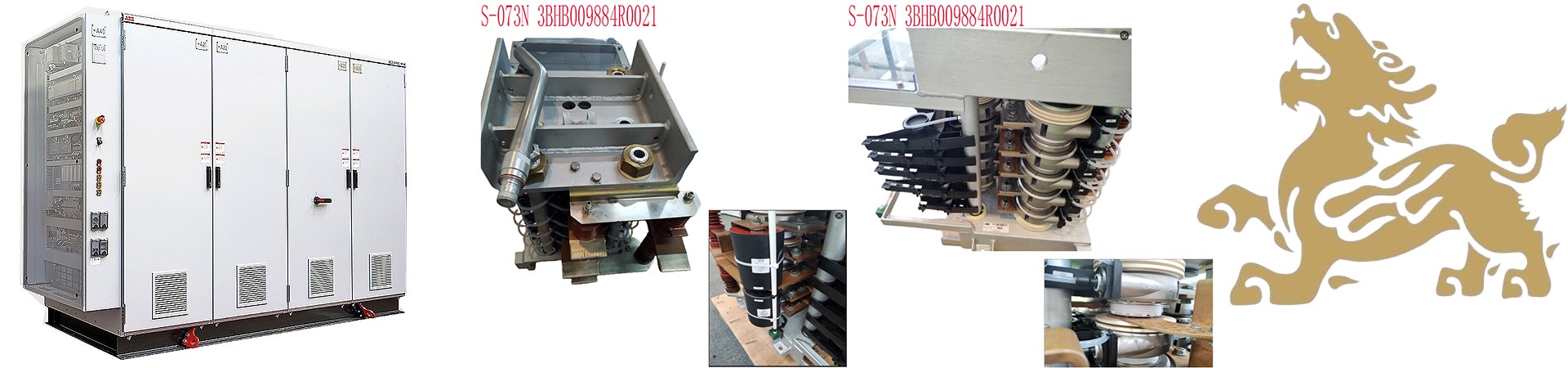
If the product model differs from the displayed image, the model number shall prevail. Please contact us for specific product images; we will arrange to take photos in our warehouse for confirmation.
We have 76 shared warehouses worldwide, so it may sometimes take several hours to accurately return the information to you. We apologize for the inconvenience. Of course, we will respond to your inquiries as soon as possible.
Marine Monitoring Relays are specialized protection and monitoring devices for marine power distribution and generator systems. They collect parameters such as voltage, current, power, and insulation through CT/PT, compare them with set thresholds, and output alarm or trip signals. They meet classification society certification standards and are suitable for marine environments with vibration, high humidity, and salt spray.
I. Core Functions
Real-time Parameter Monitoring: Continuously collects electrical quantities to monitor the operating status of generators, buses, and loads.
Fault Diagnosis: When operating parameters exceed the set range, internal logic determines a fault.
Signal Output: Relay contact output drives audible and visual alarms, circuit breaker tripping, and sends signals to the PMS power management system.
Delayed Action Prevention: Configures an action delay to avoid instantaneous disturbances and prevent false tripping of the protection system.
Status Indication: Panel LEDs display normal/fault status for easy engine room inspection.
II. Working Principle:
The sensors (current transformers (CTs) and voltage transformers (PTs) collect system signals and send them to the relay; the internal circuit performs RMS (Real Maturity Sample) calculations and compares them with the threshold value set on the panel potentiometer.
Parameters within the normal range: The relay maintains its normal state, and the alarm contact does not activate.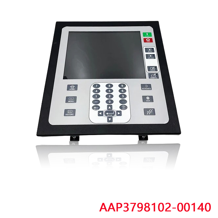
Parameters exceeding the set threshold and reaching the delay time: The relay’s internal output contact flips, sending an alarm or trip command.
After the fault is cleared: It can be automatically reset or manually reset to return to normal status.
III. Commonly Used Marine Detection Relay Types:
Reverse Power Relay:
Used for generator paralleling, detecting reverse power to prevent the generator from being driven by other units and becoming a motor, triggering trip protection. It is an essential device for marine power paralleling.
Voltage Monitoring Relay (Overvoltage/Undervoltage)
Monitors bus voltage; alarms and trips when voltage is too high or too low, protecting ship’s motors and equipment.
Insulation Monitoring Relay
In shipboard IT ungrounded systems, detects insulation resistance to the hull; alarms are triggered when insulation deteriorates, providing early warning of grounding faults and preventing short circuits and fires caused by two-point grounding.
Frequency Relay
Monitors generator frequency; trips protection when frequency is abnormal.
Differential Current Relay
Protectes internal faults in the generator stator windings; compares the current difference across the winding terminals; trips in case of inter-turn or grounding faults.
Phase Sequence/Phase Loss Relay
Detects the phase sequence and missing phases of the three-phase power supply, preventing motor reversal and burnout due to phase loss.
IV. Typical Application Scenarios
Main switchboard and emergency switchboard generator protection cabinets on ships;
Ship PMS power management system, serving as the underlying protection acquisition unit;
Circuit monitoring of high-power motors, pumps, and fans in the engine room;
Parallel operation protection of generator sets on offshore platforms, engineering vessels, and cargo ships.
V. Common Faults and Handling
False Trip: Alarm and tripping under normal operating conditions → Check setting parameters, eliminate loose wiring caused by vibration or salt spray, and recalibrate the action value.
Failure to Trip: No alarm or tripping when a fault occurs → Verify the relay, confirm whether the CT/PT signal input is normal, and replace the aging part directly with a spare.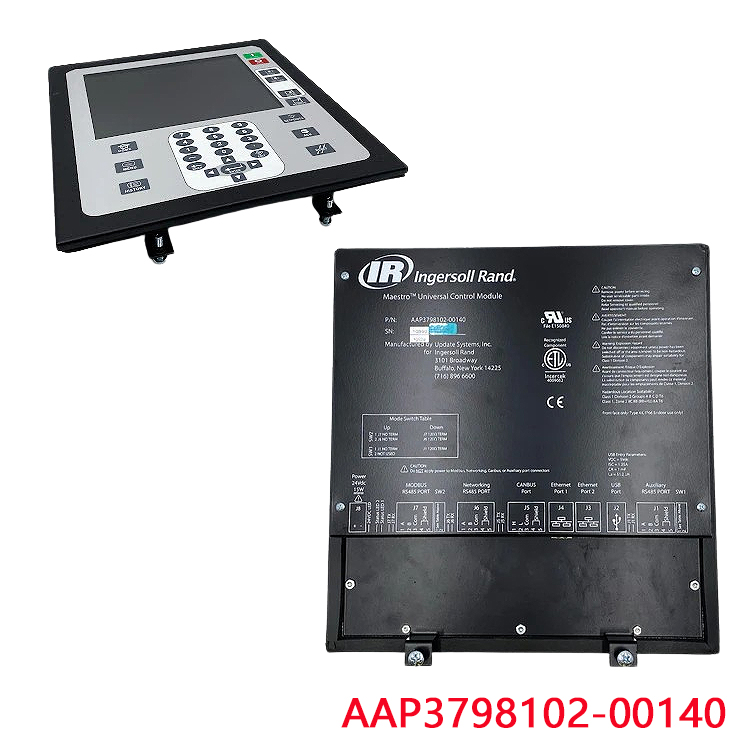
Contact Damage: Contact erosion, no signal output → Replace with spare parts on board.
Parameter Drift: Long-term salt spray and vibration cause deviation in action threshold → Regularly calibrate and recalibrate according to the requirements of the classification society.
VI. Overall Workflow
1. Signal Acquisition
The high-voltage, high-current signal from the main generator/distribution board is converted into a low-voltage, small signal and sent to the relays via current transformers (CTs) and voltage transformers (PTs). Insulation relays acquire the hull-to-ground insulation signal through their internal measurement circuits.
2. Signal Processing and Comparison
The internal circuits rectify and process the acquired signals, converting them into actual voltage, current, power, and insulation resistance values, and compare them with the threshold values set on the panel.
3. Delay Judgment (Preventing False Trips)
Instantaneous impact disturbances can occur in the ship’s electrical network, and the relays have an operating delay.
Only when the fault condition persists for more than the set delay time is it considered a real fault, filtering out instantaneous fluctuations and preventing false tripping of the protection system.
4. Contact Output Action
Normal State: The internal output relays remain in normal operation, the alarm and trip contacts maintain their original state, and the signal sent to the PMS system receives no alarm.
Fault Status: When parameters exceed limits and a delay occurs, the internal electromagnetic relay/electronic output contact flips, outputting a switching signal, driving an audible and visual alarm, disconnecting the circuit breaker, and reporting to the power management system.
5. Fault Reset
Automatic reset after fault clearance; critical protection (reverse power, differential) generally requires manual reset, resuming operation only after confirming fault clearance.
6. Brief Distinction Between Different Types of Relays
Reverse Power Relay: Collects voltage and current to calculate the direction of active power. When power is reversed (generator driven by the grid), it trips the generator switch after a delay.
Overvoltage/Undervoltage, Frequency Relay: Directly collects PT voltage signals and compares them with upper and lower voltage and frequency thresholds for protection.
Insulation Monitoring Relay (IT System): Injects measurement signals into the ship’s ungrounded power grid, calculates the insulation resistance value between the grid and the ship’s hull, and outputs an alarm when the insulation resistance is below the threshold.
Differential Current Relay: Compares the current at both ends of the CT winding; an internal fault results in a current difference, triggering the set value.
Phase sequence loss relay: monitors the phase relationship of the three-phase voltage and triggers protection when the phase sequence is disordered or one phase is lost.
Recommended related products:
TERASAKI ERM-212-K-751-259-002-21
TERASAKI ELECTRIC ESV-1 STABILIZED
TAKENAKA ELECTRONIC 2810-I2G4
TAKENAKA ELECTRONIC 2803-I2G4
SIEMENS 3RP1505-1AW30
SHINKO SPR SPEED
SHINKO SK-DTD
SHINKO OSR OVER
SHINKO DA
SHINKO AMR TURBINE ROTOR
More……

Reviews
There are no reviews yet.