Description
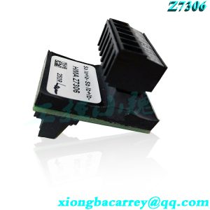
The F35 controller related to product description and safety is a compact system located in a metal casing, with 24 digital inputs, 8 digital outputs, 2 counters, and 8 analog inputs. There are three models of controllers available for SIL worX, and three models can be selected from ELOP II factory, as shown in Chapter 3.2. This manual explains all variants. This device is suitable for installation in explosion-proof zone 2, see Chapter 4.1.5. This device has passed TOV certification and can be used for safety related applications below SIL 3 (IEC 61508, IEC 61511, and IEC 62061) in various categories. 4 (EN 954-1) and PL e (EN Iso 13849-1). Further safety standards, application standards, and testing standards are provided as certificates on the HIMA website. 3.1 The safety function controller is equipped with digital inputs and outputs related to safety, counters related to safety, and analog inputs related to safety. 3.1.1
.jpg)
The safety related digital input controller is equipped with 24 digital inputs. The status (HIGH, LOW) of each input is signaled by a single LED. The input signal is captured as an analog measurement value and serves as the range of INT values from… 3000 0.. 0 volts). The configurable threshold is used to generate BOOL values, as shown in Table 26. The default setting is: Low level:<7 V High level:>13 V Use system parameters to set the threshold, taking into account security related accuracy, as shown in Tables 43 and 44. Potential free mechanical connection signal power connection diagram 1: Connection with safety related digital inputs. For external wiring and sensor connections, the principle of power outage and tripping ethics should be applied. Therefore, if a fault occurs, the input signal will be in a power outage and safe state (low level). The external live wire is not monitored, but an open circuit is considered a safe low level. If the device detects a fault on the digital input when a fault occurs, the user program is based on the principle of powering off to the cutting-edge. Device activation fault indicator light. In addition to channel signal values, user programs must also consider corresponding error codes.
The error code allows the user to configure additional fault responses in the user program. Line control cannot be configured for F35 systems, such as emergency stop inputs that comply with Cat. 4 in accordance with EN 954-1. Line monitoring can be performed on digital outputs, as shown in Chapter 3.1.4.1. The safety related counter controller is equipped with two independent counters, which can be configured to input voltage levels of 5V or 24V. The required voltage level is determined by a user program with a counter [0x]. 5/24 volt mode system parameters. Input A is the counter input, B is the counting direction input, and input Z (zero track) is used for resetting. Optionally, all inputs are 3-bit Gray code inputs (in decoder operation), which can achieve the following operating modes: ● Counter function 1 (depending on the input signal in the counting direction) ■ Counter function 2 (not depending on the input signal in the counting direction) ■ Decoder operation with absolute rotation converter. For instructions on counter configuration, please refer to Chapter 3.4.4. Safety related counters have a 24 bit resolution, The maximum counter reading is 22 “-1 (=16 777215). The response when a fault occurs. If the device detects a fault in the counter section, it is in the user program. The device activates the fault indicator light. In addition to the status bit, the user program must also consider the corresponding error password error code to allow the user to configure additional fault responses in the user program. The resolution of voltage and current values depends on the properties of the controller. In SILworX, it can be done in the Module Select FS 1000/FS 2000 system parameters (digital and analog input module MI 24/8) in the (Module) tab. According to the selection, different resolutions generate ->value [INT] system parameters in the user program. Please refer to Chapter 4.3.4.1. To monitor ->value [INT] parameters, please evaluate the corresponding ->error code [BYTE] fault value in the user program. In the ELOP II factory, set 1000 resolution (MI 24/8 FS 1000) or 2000 resolution (MI 24/8FS 2000) (menu: Properties, module: Analog Input). Depending on the selection, different resolutions can result in user programs for Al [xx]. The value system parameters can be found in Chapter 4.4.4. Monitor aluminum [xx]. The Value parameter evaluates the corresponding AllxxJ.Error Code parameter in the user program. Evaluate the input signal based on the principle of power outage tripping. Only shielded cables with a maximum length of 300 meters can be connected to analog inputs. Each analog input must be connected to a pair of twisted pairs. This shield must be connected to the controller and the sensor housing, and one end must be grounded to the controller side to form a Faraday cage. Unused analog inputs must be short circuited. If there is an open circuit during the voltage measurement process (the line is not monitored), any input signal is at the high resistance input. The input voltage resulting in value fluctuations is unreliable. Therefore, for voltage input, the channel must be terminated with a 10kQ resistor. It is necessary to consider the internal resistance account of the power supply for current measurement of parallel shunts, and a 10kQ resistor is not mandatory. The design of an analog input with a common grounding L-analog input can maintain metering accuracy for 10 years. A. Recalibration must be carried out every 10 years.
Model recommendation:


Jeri Hoag –
With every thing that seems to be developing within this particular subject material, a significant percentage of perspectives tend to be somewhat stimulating. Nevertheless, I am sorry, but I can not subscribe to your whole strategy, all be it exciting none the less. It looks to everyone that your commentary are not totally validated and in simple fact you are generally yourself not thoroughly certain of the argument. In any event I did take pleasure in reading it.
Martin Chenard –
This website online can be a walk-by means of for all the data you wished about this and didn’t know who to ask. Glimpse right here, and also you’ll positively uncover it.