
Description
Many products have not yet been listed online; please contact us for more information.
If the product model differs from the displayed image, the model number takes precedence. Please contact us for specific product photos; we can arrange for warehouse staff to take and verify them.
We operate 76 shared warehouses globally, so it may sometimes take a few hours to provide an accurate response; we appreciate your understanding. Rest assured, we will address your inquiries as quickly as possible.
Product Overview
The IS420ESWBH2A is an unmanaged IONet industrial Ethernet switch designed for GE Mark VIe / Mark VIeS turbine control systems. Part of the ESWB series, it features 16 x 10/100Base-TX RJ45 copper ports and 2 x 100Base-FX multimode LC fiber-optic ports, supporting transmission distances of up to 2 km over fiber links. Developed specifically for the GE IONet real-time control network, it serves as a data exchange hub between unit controllers and remote I/O racks. It supports both DIN-rail and panel mounting, meeting the networking requirements for long-distance cabinet-to-cabinet connections in power plants and oil & gas facilities. As an unmanaged switch, it comes with factory-embedded IONet-specific forwarding logic; it does not support IT-style management features such as web-based configuration or VLANs and cannot be used as a standard office switch.
Operating Principle
The IS420ESWBH2A utilizes a store-and-forward switching architecture. It is compatible with IEEE802.3, IEEE802.3u, and IEEE802.3x standard Ethernet protocols and is deeply optimized for IONet deterministic control traffic.
Automatic MAC Address Learning: It features a built-in 4K MAC address table that automatically identifies the MAC addresses of controllers and I/O modules within the IONet network. It establishes mappings between ports and device addresses to ensure precise packet forwarding, suppress broadcast traffic flooding, and prevent broadcast storms from disrupting the unit control network. Frame Buffering and Queued Forwarding: Features a minimum 256KB packet buffer. It buffers and queues packets during concurrent multi-port ingress and forwards them after frame-by-frame validation. This minimizes packet collisions and loss, ensuring stable timing for the transmission of real-time messages such as turbine protection signals and servo commands.
Port Auto-Negotiation Mechanism: All RJ45 copper ports support 10/100Mbps speeds and full/half-duplex auto-negotiation. Integrated HP-MDIX automatic cable detection allows the direct use of both straight-through and crossover cables. Two LC multi-mode fiber ports operate at a fixed 100Mbps rate, facilitating long-distance networking across cabinets.
Diode-OR Redundant Power Supply: Dual 24/28VDC power inputs operate independently and are isolated via diodes. The system automatically switches between power sources without interruption in the event of a failure, ensuring the IONet remains online and preventing network outages caused by a single point of power failure.
Hardware LED Status Monitoring: Each copper and fiber port is equipped with indicators for link status, data transmission/reception, speed, and duplex mode. A system-wide power status indicator is also included, allowing for quick, intuitive assessment of link connectivity and communication status without the need for software login.
Product Advantages
Integrated Copper/Fiber Ports Supporting Long-Distance Networking: Combines 16 copper ports with two LC multi-mode fiber ports. Copper ports allow for local connection to nearby I/O racks, while fiber ports enable long-distance transmission of up to 2km. This solves cabling challenges in large power plants where cabinets are distributed across wide areas, making it a key model in the ESWB series for fiber-extended networking. Dedicated real-time forwarding for turbines, featuring low latency and high determinism: Hardware forwarding logic is optimized for Mark VIe IONet control packets, ensuring stable forwarding latency and deterministic transmission of critical signals—such as unit speed, pressure, valve control, and trip protection—without the packet jitter issues common in standard commercial switches.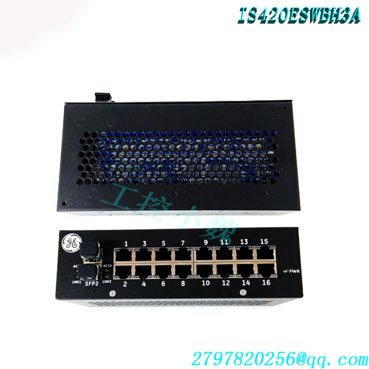
Wide-temperature, high-reliability industrial hardware: Operates within a temperature range of -40°C to +70°C and relative humidity of 5%–95% (non-condensing); meets G3 corrosion resistance standards; resistant to vibration and shock; and capable of withstanding harsh power plant cabinet environments characterized by high temperatures, dust, and strong electromagnetic interference. It boasts a high MTBF, making it suitable for continuous, year-round operation.
Dual-redundant DC power architecture: Features two independent 24/28VDC power inputs (TB1 and TB2) with a diode-isolated redundant design; failure of a single power circuit does not interrupt device communication, thereby reducing the risk of unplanned unit shutdowns and aligning with high-availability control principles for power equipment.
Configuration-free, unmanaged design for easy O&M: Operates immediately upon power-up with no network parameter configuration required; supports auto-negotiation on ports, allowing for field replacement of spare parts without commissioning, which minimizes downtime for repairs.
Flexible installation and reliable interfaces: Supports DIN-rail mounting or screw-based backplane/panel mounting; RJ45 ports withstand up to 200 mating cycles, ensuring durability; features an IP20-rated housing with natural convection cooling, eliminating the need for additional fans.
Applicable Industries and System Functions
Applicable Industries
Gas/Steam Combined-Cycle Thermal Power: Mark VIe control systems for gas and steam turbines
Petrochemical Industry: Captive power plants and turbine-driven compressor units
Oil & Gas Extraction: Gas turbine generator sets and power control systems for offshore platforms
Combined Heat and Power (CHP), industrial power stations, and hydroelectric turbine control systems
Functions within the Control System
IONet Hybrid Fiber-Copper Network Switching Core: Serves as the internal I/O network hub for the Mark VIe system, enabling bidirectional, real-time data exchange between main controllers, remote I/O modules, and protection modules; copper ports connect to local racks, while fiber-optic ports facilitate network expansion across different equipment rooms and long-distance cabinets.
Network Fault Isolation and Broadcast Storm Suppression: Uses MAC address tables for targeted packet forwarding, confining local network anomalies to a single port to prevent faults from spreading to the entire unit control system, thereby safeguarding unit protection logic.
Control Node Expansion and Distributed I/O Network Setup: 16 RJ45 ports allow for the connection of numerous I/O racks, while fiber-optic ports extend network range, meeting the networking requirements for wide-area signal acquisition and control output in large-scale turbine units.
Ensuring Unit Protection Loop Continuity: Utilizes redundant power supplies to maintain IONet connectivity even during single-point power distribution failures within the cabinet, ensuring reliable transmission of emergency trip and protection interlock signals, and reducing equipment downtime incidents.Operating Procedures
1. Pre-installation Preparation
① Ensure power is disconnected throughout the operation and wear an anti-static wrist strap to prevent electrostatic damage to circuit board chips; ② Verify the model number (IS420ESWBH2A) and inspect the housing, RJ45 ports, and LC fiber-optic interfaces for damage or deformation; ③ Confirm that the cabinet’s ambient temperature and humidity meet specifications and that the cabinet grounding system is intact; ④ Prepare Cat5e shielded twisted-pair (STP) cables and GE-compatible multimode LC fiber-optic cables; ensure the length of a single copper cable segment does not exceed 100 meters and the multimode fiber link does not exceed 2 km.
2. Hardware Installation
① DIN rail mounting: Attach the OEM mounting clip to the switch housing, snap it onto the cabinet’s DIN rail, and lock it in place; Panel mounting: Secure the module directly to the cabinet backplane using mounting screws; ② Power wiring: Connect two 24/28VDC power sources to power terminals TB1 and TB2 respectively, strictly observing polarity; ③ Cable connection: Connect the RJ45 port to the Mark VIe controller and the I/O rack IONet port; connect the LC fiber-optic port to the remote switch’s fiber port; ground the shield of the shielded network cable at one end only, and ensure dust protection for fiber-optic connectors.
3. Power-up and Status Check
① Power on the unit after confirming all wiring is correct; ② A steady power LED indicates normal power supply; ③ Port LED check: A steady link light indicates a connected physical link, while a flashing light indicates data transmission/reception; green indicates 100 Mbps, and yellow indicates 10 Mbps; observe the link indicator status for fiber-optic ports as well; ④ Use the ControlST software at the system level to scan the Mark VIe system and confirm that all IONet nodes are communicating normally with no network alarms.4. Spare Part Replacement Procedure
① Disconnect both power supply lines to the module while ensuring unit safety; ② Record the cable ID corresponding to each RJ45 and fiber-optic port, then disconnect the network cables, fiber-optic cables, and power terminals in sequence; ③ Remove the old module and install the new IS420ESWBH2A; ④ Reconnect the network cables, fiber-optic cables, and power wiring according to the recorded information; ⑤ Power on the unit, verify the port LED status, and use ControlST to validate IONet network communication.
Precautions
Electrostatic Protection: The module contains components sensitive to static electricity; an anti-static wrist strap must be worn during handling and installation/removal. Do not touch the circuit board’s metal contacts directly. Store spare parts in anti-static, sealed packaging.
No Substitution with Standard Switches: The IS420ESWBH2A is a dedicated switch for the Mark VIe IONet; replacing it with a standard commercial switch is strictly prohibited. Standard switches cannot meet IONet real-time timing requirements, which would lead to communication anomalies and spurious protection trips.
Grounding and Cabling Specifications: Ground the shield of the shielded twisted-pair cable at a single point only; do not ground both ends simultaneously, as this creates ground loops that introduce electromagnetic interference and cause intermittent packet loss. Route network and fiber-optic cables away from high-power industrial power cables to minimize interference.
Fiber-Optic Port Protection: LC fiber-optic interfaces are highly susceptible to dust contamination; install dust caps on all unused ports. Keep fiber-optic end-faces clean during connection and disconnection; contamination can cause optical signal attenuation and communication failure.
Power Supply Requirements: Connect only to a 24/28 VDC industrial power supply; connection to AC mains power is strictly prohibited. Use two independent power sources to maximize redundancy and fault tolerance. Environmental Heat Dissipation Requirements: Avoid installation in areas exposed to corrosive gases, excessive dust, or strong vibrations. The module relies on natural convection for heat dissipation; ensure adequate ventilation space around the unit and do not enclose or seal it.
No Unauthorized Opening or Repair: The module contains no user-serviceable parts; do not open the casing. Opening the unit voids the warranty and creates a high risk of hardware damage. In the event of a malfunction, the entire module must be replaced.
Safety During Online Maintenance: Do not plug or unplug IONet cables or fiber optic cables while the unit is powered on or operating. Such operations must only be performed when the unit is shut down or the system is in offline maintenance mode to prevent triggering a protective trip.
Spare Parts Storage: Store spare parts in an environment with a temperature range of -40°C to +85°C; ensure the environment is dry and free from condensation.
Model recommendation:
IS420UCSCH1B
IS420ESWBH3A
IS420UCSBH1A
IS420ESWBH3A-C
IS420YAICS1B
IS420UCSBS1A
IS420ESWBESWB
IS420UCSCH2A-E-V0.1-A
IS420UCSBH3A-UCSB
IS420UCSBS1A-UCSB
A100C08013.0100-0934 MOTHERBOARD
UTL-MB01-1154A MOTHERBOARD
7565-1 MOTHERBOARD
A100C08013.0100-0934 MOTHERBOARD
CMA-120 BASIC
IS200ESELH1A
IS220UCSAH1A
IS200AEPGG1AAA
IS200TSVCH2AED
IS215UCCCM04AB
IS220PDIOH1A
IS220PPROS1B
IS200EPMCH1
IS215UCCAH3A
IS200JPDGH1A
IS420UCSBH1a
IS415UCVHH1A
IS215UCVHM06A
IS415UCVHH1AB
IS420UCSCS2A-B-V0.1-A
IS41ySUAAH1A
IS410BAPBH1A
IS41yJPDEG1A
IS41yJPDDG4A
more……


admin –
The IS420ESWBH2A device is an unmanaged IONet/Industrial Ethernet switch designed by General Electric to be used in either Mark VIeS or Mark VIe Safety Control Systems. A key defining feature of the differences between the five ESWB switches is the number of fiber ports on the switch; this switch has two 100Base-FX multi-mode fiber ports, no matter what type of mode the fiber port has an LC-type connection. A special feature regarding the RJ45 connectors is that they have the ability to handle high amounts of stress and should be able to be used with up to two hundred insertion/removal cycles.https://www.weikunfadacai1.com/
admin –
Since high reliability is needed when using the IS420ESWBH2A switch there are several performance criteria that should be considered during operation, switch architecture, inrush current, and switch latency. The inrush current of the switch will provide a soft start that will help to limit the inrush current to less than two hundred percent of the normal operating current.
IS420ESWBH2A is an Ethernet IONet Switch manufactured by General Electric as part of the Mark VIe Series used in gas turbine control systems. All IONet switches utilized in a Mark VIe and Mark VIeS Safety control system must be from GE’s product line of industrial, unmanaged Ethernet 10/100 switches, specifically designed to satisfy the needs of real-time industrial control solutions.
admin –
The IS420ESWBH2A is an IONet industrial Ethernet switch within the GE (now GE Vernova) Mark VIe / Mark VIeS control system, belonging to the IS420 ESWB (Ethernet Switch B) family. This switch features a Layer 2 unmanaged, plug-and-play design and facilitates real-time network communication between controllers and I/O modules within the Mark VIe distributed control network.
Port Configuration (Key Feature of This Model)
According to official GE Mark VIe system documentation, the primary distinction between models in the ESWB family lies in the number of fiber-optic ports. The configuration for the IS420ESWBH2A is as follows:
16 x 10/100Base-TX copper RJ-45 ports: Used to connect in-cabinet devices such as controllers, I/O packs, and HMIs; supports auto-negotiation (speed/duplex) and Auto-MDIX;
2 x 100Base-FX multimode fiber-optic ports (LC connectors): Used for backbone cascading across cabinets or interconnecting distant network segments; offers high electromagnetic interference (EMI) immunity, making it suitable for environments with strong electromagnetic fields, such as generator rooms;
Compliant with IEEE 802.3 / 802.3u / 802.3x standards; features a 4K MAC address table and a minimum buffer size in the 256 Kb range.
Role in the System
Handles node-level switching for the Mark VIe IONet real-time control network, connecting controllers (e.g., UCSB, UCSC, UCDH) with distributed I/O modules and carrying real-time protocols such as EGD (Ethernet Global Data);
Supports dual-IONet redundancy (Network A/B) architecture, enabling control communication redundancy through a dual-network deployment;
Engineered to handle high-frequency IONet UDP multicast traffic, ensuring deterministic communication and packet integrity during transient turbine operating conditions;
The two fiber-optic ports make it particularly suitable for interconnecting IONet backbones across multiple cabinets or for applications requiring fiber transmission over long distances or in high-interference environments.
https://www.weikunfadacai1.com/product/is420eswbh2a-ge/
admin –
Precautions
Electrostatic Protection: The module contains components sensitive to static electricity; an anti-static wrist strap must be worn during handling and installation/removal. Do not touch the circuit board’s metal contacts directly. Store spare parts in anti-static, sealed packaging.
No Substitution with Standard Switches: The IS420ESWBH2A is a dedicated switch for the Mark VIe IONet; replacing it with a standard commercial switch is strictly prohibited. Standard switches cannot meet IONet real-time timing requirements, which would lead to communication anomalies and spurious protection trips.
Grounding and Cabling Specifications: Ground the shield of the shielded twisted-pair cable at a single point only; do not ground both ends simultaneously, as this creates ground loops that introduce electromagnetic interference and cause intermittent packet loss. Route network and fiber-optic cables away from high-power industrial power cables to minimize interference.
Fiber-Optic Port Protection: LC fiber-optic interfaces are highly susceptible to dust contamination; install dust caps on all unused ports. Keep fiber-optic end-faces clean during connection and disconnection; contamination can cause optical signal attenuation and communication failure.
Power Supply Requirements: Connect only to a 24/28 VDC industrial power supply; connection to AC mains power is strictly prohibited. Use two independent power sources to maximize redundancy and fault tolerance. Environmental Heat Dissipation Requirements: Avoid installation in areas exposed to corrosive gases, excessive dust, or strong vibrations. The module relies on natural convection for heat dissipation; ensure adequate ventilation space around the unit and do not enclose or seal it.
No Unauthorized Opening or Repair: The module contains no user-serviceable parts; do not open the casing. Opening the unit voids the warranty and creates a high risk of hardware damage. In the event of a malfunction, the entire module must be replaced.
Safety During Online Maintenance: Do not plug or unplug IONet cables or fiber optic cables while the unit is powered on or operating. Such operations must only be performed when the unit is shut down or the system is in offline maintenance mode to prevent triggering a protective trip.
Spare Parts Storage: Store spare parts in an environment with a temperature range of -40°C to +85°C; ensure the environment is dry and free from condensation.