
Description
All products on this site are specialized items subject to fluctuating market prices.
Please rely on the quote provided by customer service, as the listed prices are not final.
Before placing an order, please confirm details such as the model, product specifications, and pricing with customer service.
Please contact customer service for further discussion regarding these products.
I. Product Overview
The MOOG G123-825-001 (IN123-825-001) is a compact, DIN-rail mountable buffer amplifier from MOOG, belonging to the G123 series of analog interface products. It is designed to resolve signal compatibility issues between standard signal sources (such as PLCs or servo amplifiers) and MOOG servo valves or proportional valves in industrial control systems. It performs three core functions: signal conversion, active filtering, and drive adaptation.
The module operates on 24V DC power, supports various analog input signals, and allows for flexible configuration of output signal types via panel switches. It is widely used in industrial servo control, hydraulic testing equipment, the retrofitting of legacy hydraulic systems, and automation applications requiring high signal precision and robust interference immunity. Its most significant value lies in enabling a seamless upgrade from traditional Mechanical Feedback (MFB) servo valves to modern Electrical Feedback (EFB) servo valves without replacing the existing servo amplifier, thereby significantly reducing system retrofit costs and downtime.
II. Operating Principle and Signal Flow
The operation of the G123-825-001 can be divided into five sequential stages: the signal enters from the input side, undergoes internal processing, and is then output to drive the servo valve. 1. Signal Input
Control command signals from a PLC or a host servo amplifier enter the module via input terminals. The module supports three types of input signals: voltage input (0 to ±10 VDC; input impedance 100 kΩ, switchable to 1 kΩ low-impedance mode); current input (4 to 20 mA; input impedance 50 Ω); and the 0 to ±100 mA current signal used by traditional MFB (Mechanical Feedback) servo valves. This multi-type input design ensures compatibility with virtually all mainstream industrial analog output cards.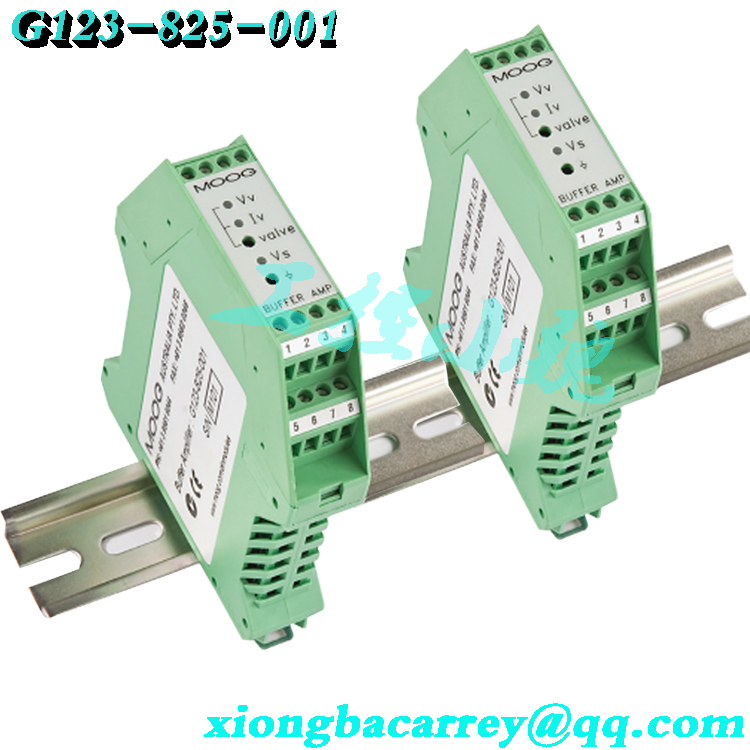
2. Active Filtering
The input signal first enters the Valve Command Filter. This filter is a single-pole active low-pass filter; its cutoff frequency is selected via various combinations of the internal switch S2. Available settings include 7 Hz, 16 Hz, 34 Hz, 72 Hz, and 723 Hz, corresponding to time constants of approximately 22 ms, 10 ms, 4.7 ms, 2.2 ms, and 0.22 ms, respectively. Since the settings have a cumulative effect, field engineers can combine them to achieve various filtering time constants based on the actual intensity of electromagnetic interference. This effectively filters out high-frequency noise, spikes, and contact bounce found in industrial environments, ensuring the purity of the command signal.
3. Signal Conversion and Integrated Amplification
The filtered signal proceeds to the integrated amplifier stage. The module contains both voltage and current amplifier channels, converting the input signal into a voltage or current drive signal compatible with downstream MOOG valves. In applications involving the upgrade from MFB to EFB (Electrical Feedback) technology, this stage also performs signal format conversion—transforming the drive current (originally intended for mechanical feedback valves) into a signal compatible with modern electrical feedback valves. The output current selector switch supports the simultaneous selection of multiple ranges; for instance, selecting both the 30mA and 50mA settings yields a full-scale output current of ±80mA, allowing for precise matching of the rated current requirements of various servo valve models.
4. Drive Output
The converted drive signal is transmitted via output terminals to the downstream MOOG servo valve or proportional valve. The voltage output range is 0 to ±10VDC (minimum load impedance: 1kΩ). Current output options include a fixed 4–20mA range (maximum load: 500Ω) and selectable, stackable ranges of 0 to ±5/10/20/30/50mA (maximum output: ±100mA). The module also provides an auxiliary ±15VDC power output via terminals 12/16—with a maximum current capacity of 110mA minus the maximum valve current—for use by field sensors or low-signal circuitry.
5. Status Monitoring and Protection
The module monitors input and output status in real time. Three LED indicators are provided on the front panel: Vs indicates power status (green; remains lit when power is normal); Vv indicates voltage output (dual-color red/green, representing positive and negative voltage outputs respectively, with maximum brightness at ±10V); and Iv indicates current output (dual-color red/green, with maximum brightness in the ±5mA to ±100mA range). The panel also features a valve drive signal test point (10kΩ output impedance), allowing for direct observation of drive waveforms using an oscilloscope or multimeter in the field. Built-in overcurrent and short-circuit protection automatically cuts off the output during anomalies, protecting both the module itself and the downstream valve.
III. Technical Advantages
As a mature model within Moog’s analog interface product line, the G123-825-001 offers technical advantages in the following areas:
1. Robust Signal Compatibility
On the input side, it supports ±10V voltage, 4–20mA standard current, and MFB current signals; on the output side, it supports ±10V voltage, 4–20mA current, and multi-range, stackable current signals, ensuring compatibility with virtually the entire range of Moog servo valves and proportional valves. This highly flexible signal configuration capability makes it a universal bridge connecting Moog valves with control systems from various manufacturers and eras.
2. Cost-Effective System Upgrading
This is the product’s most distinctive advantage. When retrofitting legacy hydraulic equipment, the traditional approach involves replacing both the MFB servo valve and the servo amplifier, resulting in high costs and long project timelines. The G123-825-001 allows for the retention of existing servo amplifiers and control systems; by simply installing this buffer module in the signal path, an MFB valve can be replaced with a higher-performance, higher-precision EFB valve, thereby significantly reducing retrofit costs and minimizing downtime.
3. Multi-stage active filtering for interference suppression
It features a built-in, five-level stackable single-pole active filter. This allows for precise adjustment of the filter bandwidth based on the frequency characteristics of on-site interference sources—such as variable frequency drives (VFDs), contactors, and welding equipment—maximizing noise suppression while maintaining system dynamic response. It is particularly well-suited for industrial environments with complex electromagnetic conditions.
4. Compact and reliable industrial design
The module utilizes a compact 22.5mm-wide DIN-rail mount design, enabling high-density installation within space-constrained control cabinets. It supports a wide supply voltage range (22–28 VDC) and includes protections against overcurrent, short circuits, and reverse polarity. It holds CE certification (compliant with EN50081.1 emission and EN50082.2 immunity standards) and C-tick certification (AS4251.1). With an IP20 protection rating, it ensures stable, long-term operation in industrial control cabinet environments.
5. Convenient on-site commissioning and maintenance
Front-panel LED indicators and test points allow technicians to verify power status, output polarity, and signal amplitude without disconnecting terminal blocks. Configuration is handled via switches—eliminating the need for programming or specialized software—so standard electrical personnel can perform parameter settings, significantly lowering the barrier to entry for commissioning and reducing maintenance costs.
Information verified. A key point must be clarified at the outset: according to MOOG’s official product classification (IN123-825 Buffer Amplifier), the G123-825-001 is not a power amplifier designed to drive servo motors directly; rather, it is a signal buffering and conversion interface module installed between the PLC/servo amplifier and the MOOG servo valve/proportional valve. The following article has been written based on this accurate classification and is ready for direct publication on your website.
MOOG G123-825-001 Servo Buffer Amplifier: A Comprehensive Analysis of Operating Principles, Technical Advantages, and Industry Applications
I. Product Overview
The MOOG G123-825-001 (official model designation IN123-825-001) is a compact, DIN-rail mountable buffer amplifier introduced by MOOG, belonging to the G123 series of analog interface products. It is specifically designed to resolve signal compatibility issues between standard signal sources (such as PLCs or servo amplifiers) and MOOG servo valves or proportional valves, performing three core functions: signal conversion, active filtering, and drive adaptation.
Powered by 24VDC, the module supports various analog input signals and allows for flexible configuration of output signal types via front-panel switches. It is widely used in industrial servo control, hydraulic testing equipment, the retrofitting of legacy hydraulic systems, and automation applications requiring high signal precision and robust interference immunity. Its most significant value lies in enabling the seamless upgrade from traditional Mechanical Feedback (MFB) servo valves to modern Electrical Feedback (EFB) servo valves without replacing the existing servo amplifier, thereby significantly reducing system retrofit costs and downtime.
II. Operating Principle and Signal Flow
The operation of the G123-825-001 can be divided into five sequential stages: the signal enters via the input side, undergoes internal processing, and is then output to drive the servo valve.
1. Signal Input
Control command signals from a PLC or a host servo amplifier are connected to the module via input terminals. The module supports three types of input signals: voltage input (0 to ±10 VDC, with an input impedance of 100 kΩ—switchable to a 1 kΩ low-impedance mode); current input (4 to 20 mA, with an input impedance of 50 Ω); and the 0 to ±100 mA current signal used by traditional MFB servo valves. This multi-type input design ensures compatibility with virtually all mainstream industrial analog output cards.
2. Active Filtering
The input signal first enters the Valve Command Filter. This filter is a single-pole active low-pass filter. Its cutoff frequency is selected via various combinations of the internal switch S2; available settings include 7 Hz, 16 Hz, 34 Hz, 72 Hz, and 723 Hz, corresponding to time constants of approximately 22 ms, 10 ms, 4.7 ms, 2.2 ms, and 0.22 ms, respectively. Since the settings have a cumulative effect, field engineers can combine them to achieve various filtering time constants based on the actual intensity of electromagnetic interference. This effectively filters out high-frequency noise, voltage spikes, and contact bounce found in industrial environments, thereby ensuring the purity of the command signal.
3. Signal Conversion and Integrated Amplification
The filtered signal proceeds to the integrated amplifier stage. The module contains both voltage and current amplifier channels, converting the input signal into a voltage or current drive signal compatible with downstream MOOG valves. In applications where an MFB (Mechanical Feedback) valve is upgraded to an EFB (Electrical Feedback) valve, this stage also performs signal format conversion: it converts the mechanical feedback valve drive current output from the existing servo amplifier into a signal compatible with modern electrical feedback valves. The output current selection switches support multi-range summation; for instance, simultaneously selecting the 30mA and 50mA ranges yields a full-scale output current of ±80mA, thereby precisely matching the rated current requirements of various servo valve models.
4. Drive Output
The converted drive signal is transmitted via output terminals to the downstream Moog servo valve or proportional valve. The voltage output range is 0 to ±10 VDC (minimum load impedance: 1 kΩ); current outputs include a fixed 4–20 mA range (maximum load: 500 Ω) and selectable, summable ranges of 0 to ±5/10/20/30/50 mA (maximum output: ±100 mA). The module also provides an auxiliary ±15 VDC power output via terminals 12/16—with a maximum current equal to 110 mA minus the maximum valve current—for use by field sensors or low-signal circuitry.
5. Status Monitoring and Protection
The module monitors input and output status in real time. Three LED indicators are provided on the front panel: Vs indicates power status (green; remains lit when power is normal); Vv indicates voltage output (dual-color red/green, representing positive and negative voltage outputs respectively, with maximum brightness at ±10V); and Iv indicates current output (dual-color red/green, with maximum brightness in the ±5mA to ±100mA range). The panel also features a valve drive signal test point (10kΩ output impedance), facilitating direct observation of drive waveforms on-site using an oscilloscope or multimeter. Built-in overcurrent and short-circuit protection automatically cuts off the output during anomalies, protecting both the module itself and the downstream valve.
III. Technical Advantages
As a mature model in Moog’s analog interface product line, the G123-825-001 offers technical advantages in the following areas:
1. Robust Signal Compatibility
On the input side, it supports ±10V voltage, 4–20mA standard current, and MFB current signals; on the output side, it supports ±10V voltage, 4–20mA current, and multi-range, stackable current signals, ensuring compatibility with virtually the entire range of Moog servo valves and proportional valves. This highly flexible signal configuration capability makes it a universal bridge connecting Moog valves with control systems from various manufacturers and eras.
2. Cost-Effective System Upgrading
This is the product’s most distinctive advantage. When retrofitting legacy hydraulic equipment, the traditional approach involves replacing both the MFB servo valve and the servo amplifier, resulting in high costs and long project timelines. The G123-825-001 allows for the retention of existing servo amplifiers and control systems; by simply installing this buffer module in the signal path, an MFB valve can be replaced with a higher-performance, higher-precision EFB valve, resulting in significant savings on retrofit costs and shorter system downtime.
3. Multi-stage Active Filtering for Interference Suppression
It features a built-in, five-level stackable single-pole active filter. The filter bandwidth can be precisely adjusted based on the frequency characteristics of on-site interference sources—such as variable frequency drives (VFDs), contactors, and welding equipment—to maximize noise suppression while maintaining system dynamic response. This makes it particularly suitable for industrial environments with complex electromagnetic conditions.
4. Compact and Reliable Industrial Design
The module utilizes a compact 22.5mm-wide DIN-rail mount design, allowing for high-density installation in space-constrained control cabinets. It supports a wide supply voltage range (22–28 VDC) and includes protections against overcurrent, short circuits, and reverse polarity. It holds CE certification (compliant with EN50081.1 emission and EN50082.2 immunity standards) and C-tick certification (AS4251.1). With an IP20 protection rating, it ensures stable, long-term operation within industrial control cabinet environments.
5. Convenient On-site Commissioning and Maintenance
Front-panel LED indicators and test points allow technicians to verify power status, output polarity, and signal amplitude without disconnecting terminal blocks. Configuration is handled via switches—eliminating the need for programming or specialized software—enabling standard electrical personnel to perform parameter settings, thereby significantly lowering the barriers to commissioning and reducing maintenance costs.IV. Core Technical Specifications
| Parameter Category | Technical Specification |
| — | — |
| Rated Supply Voltage | 24 VDC (Permissible range: 22–28 VDC) |
| Quiescent Current | 65 mA (no output) |
| Operating Current | 170 mA (at 100 mA output) |
| Recommended Fuse | M205 250 mA slow-blow (compliant with IEC 127-2 sheet 3) |
| Voltage Input | 0–±10 VDC, impedance 100 kΩ (switchable to 1 kΩ) |
| Current Input | 4–20 mA, impedance 50 Ω; 0–±100 mA (MFB) |
| Voltage Output | 0–±10 VDC, minimum load 1 kΩ |
| Current Output | 4–20 mA (max. load 500 Ω); 0–±5/10/20/30/50 mA (additive), max. ±100 mA |
| Input Filter | Single-pole active low-pass; selectable: 7/16/34/72/723 Hz |
| Auxiliary Power Output | ±15 VDC, max. current = 110 mA − max. valve current |
| Terminal 10 Max. Current | 500 mA (cannot power DDV valves) |
| Mounting Method | 35 mm standard DIN rail | |
| Dimensions | Approx. 22.5mm (W) × 108mm (H) × 100mm (D) |
| Operating Temperature | 0°C to 40°C |
| Protection Rating | IP20 |
| Safety Certifications | CE, C-tick |
V. Role in Various Application Industries
Although the G123-825-001 is an interface-level product, it plays a crucial role in ensuring high-precision hydraulic closed-loop control across several key industries.
1. Industrial Automation and Machine Tool Manufacturing
In CNC machine tools, machining centers, automated production lines, and packaging machinery, PLC analog output cards often cannot directly drive high-power servo valve coils. Acting as a signal relay and buffer, this module converts the PLC’s low-level voltage/current commands into the standard drive signals required by servo valves. Simultaneously, its high input impedance minimizes the load on the PLC output channels, thereby maintaining control precision for position and velocity loops.
2. Material and Structural Testing Equipment
In universal material testing machines, fatigue testing machines, vibration test stands, and hydraulic testing systems, closed-loop control of load, displacement, and strain demands extremely high signal purity. The module’s active filtering function effectively suppresses interference from nearby equipment—such as pump stations and solenoid valves—ensuring that the servo valve accurately reproduces the waveform commands issued by the controller, thereby enhancing the repeatability and reliability of test data.
3. Retrofitting of Legacy Hydraulic Systems
This is one of the most common application scenarios for this product. Many industrial machines, metallurgical equipment, and test rigs commissioned in the last century still utilize MFB (Mechanical Feedback) servo valves—valves that are now largely discontinued, suffer from a shortage of spare parts, and offer outdated performance. By installing the G123-825-001 module, users can directly upgrade to EFB (Electrical Feedback) valves while retaining their existing control cabinets and servo amplifiers; this provides superior frequency response, lower hysteresis, and enhanced null stability at a minimal cost.
4. Energy and Metallurgy Industries
In applications such as hydraulic pitch control systems for wind turbines, Automatic Gauge Control (AGC) for rolling mills, vibration suppression systems, and hydraulic servo loops on metallurgical production lines, this module serves as the signal interface between the controller and the servo valve. These environments typically involve continuous operation where downtime is costly; the module’s wide operating temperature range, interference immunity, and protective features provide a crucial safeguard for system reliability.
5. Aerospace and Defense Ground Testing
Moog servo valves are standard actuation components in high-precision, high-reliability applications such as hardware-in-the-loop (HIL) simulations for flight control systems, engine ground test rigs, and marine steering control systems. As the official interface module, the G123-825-001 ensures signal consistency and system compatibility for control commands transmitted from the cabinet to the valve.
VI. Operation and Commissioning
1. Installation
Snap the module onto a standard 35mm DIN rail, ensuring the locking mechanism is fully engaged and the unit is securely mounted. It is recommended to install the module inside the control cabinet, away from high-voltage/high-current circuits and at a sufficient distance from major sources of interference, such as variable frequency drives (VFDs) and contactors. Cable shields should be connected at the module’s cable gland to establish single-point grounding, thereby suppressing common-mode interference.2. Power Supply Wiring
Connect the 24VDC power supply to the corresponding power terminals, ensuring correct polarity. An M205 250mA slow-blow fuse of the recommended specification must be connected in series within the power supply circuit. If Terminal 10 is used to power a downstream proportional valve, the fuse rating must be increased according to the valve’s actual operating current. Note that the maximum output current of Terminal 10 is 500mA; it must not be used to power DDV (Direct Drive Valve) units.
3. Input Signal Configuration
Select the appropriate input mode via internal switches based on the output signal type of the host control system: connect to the voltage input terminal if the PLC outputs a ±10V signal; connect to the current input terminal if it outputs a 4–20mA signal; or, for MFB upgrade applications, connect to the MFB current output terminal of the original servo amplifier. Resistors R21 and R25 on the PCB (default 390kΩ, 1/4W) set the MFB input current range; these may be replaced with resistors of different values as specified in the valve manual if necessary.
4. Output Signal Configuration
Set the output mode using the output selection switches based on the input signal requirements specified on the downstream servo valve’s nameplate. For EFB valves accepting 4–20mA signals, select the fixed 4–20mA output; for those accepting ±10V signals, select the voltage output; for MFB valves or applications requiring a specific full-scale current, configure the required current value by combining the ±5/10/20/30/50mA switches. Disconnect the load power supply before configuration to prevent unintended output operation.
5. Filter Setting
Select the filter cutoff frequency based on the signal quality at the installation site. The general principle is as follows: select a higher cutoff frequency (72 Hz or 723 Hz) when the system requires high dynamic response; lower the cutoff frequency (e.g., 16 Hz or 7 Hz) to achieve stronger filtering effects when there is severe on-site interference or high-frequency valve oscillation. Settings can be combined; it is recommended to test incrementally from lower to higher values to balance response speed and signal smoothness.
6. Power-on Commissioning
Apply power after verifying that the wiring is correct. Observe the panel; the “Vs” indicator should light up green. When a zero-position command is input, the “Vv” and “Iv” indicators should be essentially off; the corresponding polarity indicator should light up when a positive command is applied, and the other polarity indicator should light up when a negative command is applied. Measure the valve drive signal at the front-end test points using a multimeter or oscilloscope to confirm that the amplitude, polarity, and linearity meet expectations. Finally, observe the valve’s direction of movement in closed-loop mode to ensure it aligns with system requirements; if the direction is reversed, adjust the command polarity in the host controller rather than altering the module’s wiring.
VII. Precautions and Safety Guidelines
1. Power Supply and Fuses
A regulated 24 VDC power supply must be used; connection to 24 VAC or other voltage levels is strictly prohibited. A slow-blow fuse must be installed in the power supply circuit; the use of standard fast-acting fuses or copper wire as a substitute is forbidden. If terminal 10 is used to provide auxiliary power to the valve, the fuse capacity must be recalculated based on the valve’s rated current; otherwise, effective overcurrent protection cannot be guaranteed.
2. Wiring and Grounding
Strictly distinguish between power, input, and output terminals according to the wiring diagram, and ensure positive and negative polarities are not reversed. Use shielded twisted-pair cables for input signals, with the shield grounded at one end only. Route power cables and signal cables separately; avoid bundling them in parallel. The module’s chassis ground terminal must be securely connected to the control cabinet’s protective earth busbar.
3. Load Impedance Limits
The minimum load impedance for voltage output is 1 kΩ; an excessively low load may cause output distortion or trigger protection mechanisms. The maximum load impedance for current output is 500 Ω; an excessively high load will prevent the current from reaching the set value. Before wiring, verify that the downstream valve coil impedance falls within the permissible range.
4. Environmental Conditions
The module has an IP20 protection rating; installation outdoors or in environments with high humidity, conductive dust, or corrosive gases is prohibited. It must be installed inside an enclosed control cabinet. The operating ambient temperature should be maintained between 0°C and 40°C; operating outside this range may affect the accuracy and service life of internal electronic components.
5. Configuration Change Safety
Before modifying any switch settings, disconnect the module’s power supply and the downstream valve enable signal to prevent sudden output changes from causing actuator malfunction. During commissioning, it is recommended to disconnect the valve’s hydraulic circuit or place the system in a safe mechanical state; reconnect the load only after confirming the signal direction and amplitude are correct.
6. Troubleshooting Points
If the Vs indicator is off, first check the supply voltage, polarity, and fuse. If Vs is on but there is no output, check whether the input signal is present and if the input switch settings are correct. If the output indicator fluctuates abnormally, increase the filtering time constant or check the grounding and shielding. If output protection is triggered, disconnect the downstream load and troubleshoot section by section to locate any short circuits; restore power only after the fault has been cleared.
7. Spare Parts and Replacements
The G123-825-001 is an established industrial product from Moog; when purchasing, verify the model number on the nameplate and packaging markings to ensure the product is a genuine original. It is recommended to stock spare modules of the same model and their corresponding fuses on-site; this ensures rapid replacement in the event of a module failure, thereby minimizing system downtime.
VIII. Conclusion
With its flexible signal configuration, reliable active filtering capabilities, and convenient MFB-to-EFB upgrade functionality, the MOOG G123-825-001 servo buffer amplifier serves a dual role as both a “signal bridge” and a powerful tool for system retrofitting in the field of industrial hydraulic servo control. For engineers and technicians who require high-precision motion control, face shortages of spare parts for legacy equipment, or wish to upgrade hydraulic servo systems cost-effectively, a thorough understanding of this module’s operating principles and commissioning procedures is essential for ensuring long-term, stable system operation.
Recommended model:
M128-010
M128-010-A001
M128-010
T161-902A-00-B4-2-2A
D136-001-001
D136-001-007
D136-001-008
D136-001-008a
D138-002-002
D136-002-005
D136E001-001
D138-002-002
G122-824-002
More……

admin –
Core Identity: An industrial-grade buffer amplifier manufactured by MOOG, a core component of servo control systems, specifically designed for hydraulic equipment, servo proportional valves, and automated control systems. Its main functions include signal amplification, noise filtering, gain adjustment, and multi-protocol signal conversion, adapting to PLC, DCS, and other industrial standard interfaces.
Technical Features: Built-in single-pole active filter (removes input noise), adjustable output current (supports 4-20mA, 0-10V, ±100mA modes), DIN rail mounting, front panel test points and LED indicators (for easy debugging), compliant with CE certification and industrial safety standards.
Core Functions:
Signal Amplification and Conversion: Converts PLC analog output (e.g., 4-20mA, 0-10V) to MOOG valve-compatible signals, supporting EFB/MFB valve signal conversion.
Noise Suppression: Built-in single-pole active filter filters input signal noise; the filter time constant is adjustable (e.g., 0-100ms range).
Multi-mode output: Supports 4-20mA fixed, 0-10V fixed, and ±100mA adjustable output to adapt to different valve requirements (e.g., EFB valves require 4-20mA, MFB valves require ±100mA).
Interface compatibility: Compatible with PLC and DCS systems, supports DIN rail mounting, dimensions approximately 16×25×12mm, weight 0.16kg.
Technical parameters and performance:
Electrical parameters:
Input signal: Compatible with standard industrial signals such as 4-20mA, 0-10V, and ±10V.
Output configuration: Switchable to 4-20mA fixed, 0-10V fixed, or ±5-100mA switching, compatible with MOOG EFB/MFB series servo valves.
Power requirements: 24V DC, power consumption approximately 65mA, operating temperature range 0°C to 85°C, humidity tolerance 0%-95%.
Protection Rating: IP20, resistant to electromagnetic interference, suitable for harsh industrial environments.
Dynamic Performance:
Frequency Response: Supports 70Hz step response, low signal delay, meeting real-time control requirements.
Accuracy: Output current accuracy ±0.1mA, stable voltage regulation, ensuring high-precision operation of the servo system.
Application Scenarios and Industry Adaptability
Typical Applications:
Industrial Hydraulic Systems: Hydraulic oil pressure control, servo proportional valve drive (e.g., MOOG D661, G761 series).
Automation Control: Integrated with PLC and DCS systems for motion control and process regulation (e.g., motor speed/position control).
Special Industries: Oil and gas (wellhead control), chemical industry (reactor pressure regulation), power industry (generator excitation), metallurgy (rolling mill hydraulic systems), shipbuilding (propeller control), etc.
Laboratory and Testing Equipment: Signal amplification and processing to improve measurement accuracy (e.g., sensor signal conditioning).
Performance Advantages: High reliability, strong anti-interference capability, multi-protocol compatibility, modular design, reducing system downtime risk and improving production efficiency.
Installation and Maintenance Recommendations
Installation Specifications:
Mount to a DIN rail, ensuring good grounding and avoiding electromagnetic interference.
Connection lines must conform to industry standards; sensor installation positions must be precisely aligned with monitoring points.
Maintenance Requirements:
Regularly calibrate the output current and check the status of connection lines and interfaces.
Clean the module surface to prevent dust/oil from affecting heat dissipation and performance.
Back up historical data for trend analysis and fault tracing.
Summary
The MOOG G123-825-001 servo amplifier is a core control component in industrial hydraulic systems, integrating signal amplification, noise suppression, interface conversion, and intelligent diagnostic functions. It is suitable for scenarios with extremely high system stability requirements, such as petroleum, chemical, power, and metallurgy industries. Its high reliability, strong scalability, and industry adaptability make it a key solution for industrial automation and hydraulic control.
https://www.weikunfadacai1.com/product/moog-m128-010-a001-2/
admin –
As a signal conversion and amplification device, it can convert signals from PLCs, servo controllers, or standard signal sources (such as ±10V, 4-20mA) into the current signals required to drive MOOG servo proportional valves, achieving precise hydraulic/pneumatic control.
High-precision control: Built-in single-pole active filter effectively filters out input signal noise, ensuring signal purity; supports P/I/P&I control modes to meet diverse control requirements.
Flexible configuration: Output signal type (current/voltage), filter time constant, and valve drive current can be adjusted via a switch to adapt to various application scenarios.
Interface compatibility: Supports direct connection with MOOG servo proportional valves (such as the D662Z series), and can convert MFB (mechanical feedback) signals to EFB (electrical feedback) signals, simplifying system upgrades.
Diagnosis and debugging: The front panel is equipped with test points, valve drive LEDs, and an “in-place” output function for easy real-time monitoring and troubleshooting.