
Description
All products on this website are specialized items subject to fluctuating market prices.
Please rely on the quote provided by customer service, as the listed prices are not definitive.
Before placing an order, please confirm details such as the model, product specifications, and pricing with customer service.
New units are available for sale; please contact customer service for details.
RS-FS-9004 other names:
Flame sensor RS-FS-9004
RS-FS-9004 ultraviolet flame sensor
Gas turbine ultraviolet detector RS-FS-9004
I. Product Overview
The RS-FS-9004 is a water-cooled ultraviolet (UV) flame detector from the Flame Tracker series by Reuter-Stokes (a GE brand now part of Baker Hughes). Designed specifically for Zone 0 explosive hazardous areas, it utilizes core Silicon Carbide (SiC) photodiode sensing technology to accurately detect the characteristic UV radiation emitted during hydrocarbon fuel combustion. It outputs a standard 4-20mA analog signal corresponding to flame intensity. Widely used for real-time flame monitoring and safety interlocking in gas turbines and industrial combustion systems, it serves as a critical detection device for ensuring combustion safety and preventing deflagration accidents in high-risk industrial environments.
II. Core Operating Principle
The RS-FS-9004 achieves flame detection based on the principle of long-wave ultraviolet (UV) spectral sensing combined with photoelectric signal conversion. Unlike traditional short-wave UV sensors, it targets the long-wave UV band—which possesses superior penetrating power—within the flame’s radiation spectrum. The complete operational workflow is as follows:
Spectral Filtering: Flame combustion emits UV radiation in specific bands. The detector’s optical window and filtering structure block stray light from interference sources such as sunlight, high-temperature objects, and electric arcs, allowing only long-wave UV light at the flame’s characteristic wavelength (approximately 310 nm) to reach the sensing unit.
Photoelectric Conversion: Upon receiving UV radiation, the built-in silicon carbide (SiC) photodiode converts the optical signal into a weak electrical signal proportional to the flame intensity via the photoelectric effect. The characteristics of long-wave UV light enable it to penetrate media such as fuel mist, water vapor, and oil mist, ensuring detection capabilities remain uncompromised by foggy or misty operating environments.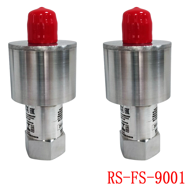
Signal Processing and Output: Internal circuitry amplifies, filters, and intelligently processes the electrical signal, ultimately outputting a standard 4–20 mA analog signal: 4 mA corresponds to a no-flame state, while 20 mA corresponds to full-scale flame intensity. Additionally, thresholds can be configured within the control system to determine flame presence/extinction status and trigger interlocking actions.
Enhanced Detection Mode: The device supports ILG (Enhanced Low Gain) mode, which increases sensitivity to low-intensity flames. This adapts the sensor to low-light conditions—such as incomplete combustion or dust accumulation on the optical window—thereby preventing missed detections.
III. Core Product Advantages
1. High Penetration and High Sensitivity
Utilizing a silicon carbide (SiC) photodiode sensor sensitive to the long-wave ultraviolet (UV) spectrum, the device penetrates operating media such as fuel mist, steam, and water vapor. It ensures stable flame detection even in high-mist environments—such as during gas turbine startup or low-load operation—thereby overcoming the limitations of traditional short-wave UV sensors, which are prone to failure due to mist obscuration.
2. Rapid Response and High Safety Redundancy
With a flame status response time of less than 25 milliseconds, the system triggers a fuel cut-off interlock the instant a flameout occurs. This prevents the accumulation of unburned gas or fuel within the combustion chamber—which could lead to deflagration—thereby providing millisecond-level safety protection for the combustion system.
3. Low Maintenance Costs and High Availability
Equipped with a quick-disconnect connector, the sensor replacement time is reduced from hours to mere minutes. An optimized heat dissipation structure combined with a water-cooling design minimizes thermal degradation of electronic components, effectively extending equipment service life and reducing unplanned downtime for maintenance.
4. Excellent adaptability to extreme operating conditions
Temperature range: Stable operation between -30°C and 150°C; compatible with water-cooling systems to withstand higher ambient temperatures;
Pressure tolerance: Supports process pressures up to 2.8 MPa (400 psig);
Housing material: Mounting interface made of AISI 316 stainless steel; housing features an argon-filled, sealed AISI 304 stainless steel structure; corrosion- and vibration-resistant; suitable for harsh environments including outdoor locations, high humidity, and corrosive gases;
Explosion-proof certification: Complies with Zone 0 hazardous area requirements; holds international certifications such as ETL, ATEX, and IECEx; meets industrial safety standards across global regions.
5. Strong system compatibility
Operates on a wide voltage range (12–30 VDC) and outputs a standard 4–20 mA industrial analog signal; connects directly to industrial control systems such as PLC, DCS, and SIS without the need for additional conversion modules; suitable for both upgrades of existing units and new installations.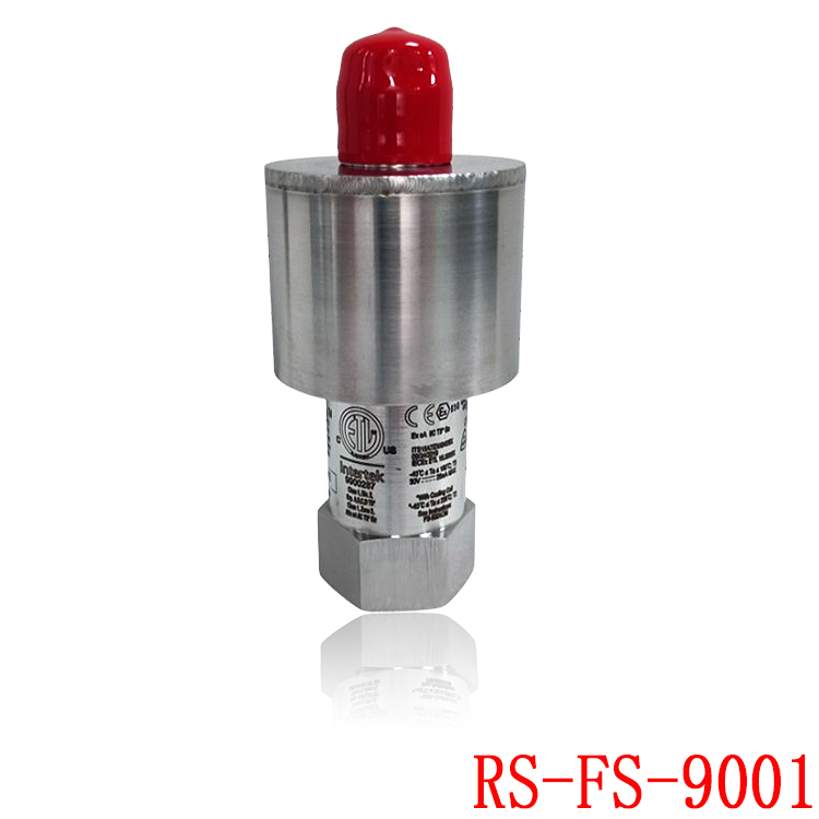
6. Low false alarm rate
Responds exclusively to the long-wave ultraviolet (UV) spectrum characteristic of flames; utilizes internal signal filtering algorithms to effectively reject environmental interference—such as sunlight, artificial lighting, hot pipe walls, and welding arcs—maintaining an extremely low annual false alarm rate.
IV. Roles and Value Across Application Industries
1. Energy and Power Industry (Gas Turbine Power Generation)
The RS-FS-9004 serves as a critical safety component for gas turbine combustion chambers, monitoring flame stability in real-time. In the event of a flameout, it triggers a fuel valve cutoff within milliseconds, preventing the accumulation of unburned natural gas that could lead to furnace deflagration. Simultaneously, reliable flame detection ensures smooth unit operation throughout the cycle, reduces unplanned downtime, and enhances power plant availability and operational efficiency; it is compatible with various combustion conditions, including low-NOx burners and steam injection systems.
2. Petrochemical Industry
Applied in scenarios such as refinery heaters, ethylene cracking furnaces, chemical reactors, and steam methane reforming units:
Safety: Integrates with Safety Instrumented Systems (SIS) to implement flameout interlocks, promptly cutting off fuel supply to prevent fires and explosions, while meeting the petrochemical industry’s rigorous explosion-proof and safety standards.
Operations: Withstands corrosion from oil and gas as well as high-temperature environments, ensuring stable, long-term operation and reducing the frequency of equipment maintenance.
3. Marine and Offshore Engineering Industry
Meets flame monitoring requirements for marine gas turbines and boilers: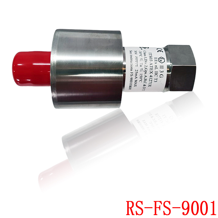
Resilience: Adapted to harsh engine room conditions characterized by high temperatures, high humidity, and intense vibration; its Zone 0 explosion-proof rating complies with installation requirements for hazardous marine zones.
Safety: Monitors the combustion status of propulsion units in real-time, ensuring safe vessel propulsion and preventing combustion-related accidents in the engine room.
4. Industrial Boiler and Hazardous Waste Incineration Industries
Flame detection for industrial power plant boilers and hazardous waste incinerators:
Ensures stable combustion within the furnace; instantly triggers a fuel-cutoff interlock upon flame loss to prevent furnace deflagration;
Provides precise flame intensity signals to assist in combustion optimization and control, thereby enhancing combustion efficiency and reducing pollutant emissions.
5. Metallurgy and Coal Chemical Industries
Applications in equipment such as blast furnace hot-blast stoves, converters, and coal gasifiers:
Real-time monitoring of gas combustion flame status; rapidly cuts off gas supply upon flame loss to prevent gas leaks that could lead to poisoning or explosions;
Withstands environments containing dust and corrosive gases, maintaining stable detection performance in heavily polluted industrial settings.
5. Standard Operating Procedures
1. Installation and Wiring
Mechanical Installation: Mount the detector at the designated observation port using the 3/4″ NPT connection, ensuring an unobstructed field of view aimed at the core flame area. For water-cooled models, connect the cooling water lines and ensure the inlet pressure and flow rate meet equipment specifications.
Electrical Wiring: Verify the power supply is 12–30 VDC. Connect the power supply lines, 4–20 mA signal output line, and shielded ground wire according to the pin definitions. After wiring, check for proper insulation and circuit continuity.
2. Power-up Self-test
Upon powering up, the detector automatically initiates a self-test sequence, during which internal circuitry checks the sensor and signal loops. Once the self-test completes without faults, the unit enters normal monitoring mode; in a no-flame state, the output signal stabilizes at approximately 4 mA.
3. Threshold Calibration
Under normal combustion conditions, read the detector’s output current via the control system and set the “Flame Present” threshold (typically 10% of full scale, corresponding to approx. 5.6 mA);
Set the “Flame Extinguished” threshold (typically 6.25% of full scale, corresponding to approx. 5 mA);
If the ILG (Low-Gain Enhancement) mode is enabled, adjust the detection thresholds downward to suit low-intensity flame conditions, ensuring weak flames are accurately detected.
4. Routine Operational Monitoring
Monitor the 4–20 mA output signal in real-time; combustion is considered normal when the signal exceeds the “Flame Present” threshold;
When the signal falls below the “Flame Extinguished” [threshold]… …threshold, the control system determines that flameout has occurred and automatically triggers interlocking actions such as fuel cutoff and alarms;
Periodically record signal fluctuations to serve as a reference for the equipment’s health status.
5. Shutdown Procedure
When shutting down the process system, first cut off the fuel supply; disconnect the detector’s power supply only after the flame inside the furnace has completely extinguished and the temperature has dropped to a safe range;
For long-term shutdowns, close the cooling water circuit and drain any residual cooling water from the piping.
VI. Installation and Operation Precautions
1. Explosion-Proof Safety Standards
When performing installation or maintenance in hazardous areas with explosion risks, strictly adhere to power-off procedures; connecting/disconnecting connectors or disassembling equipment while powered on is strictly prohibited;
Operations such as opening the housing or wiring may only be performed after confirming there is no explosion risk in the work area and that combustible gas concentrations are within safe limits.
2. Installation Environment Requirements
Ensure the detection optical path is unobstructed at the installation location, avoiding obstacles such as furnace walls or burner brackets;
Keep away from sources of strong electromagnetic interference (e.g., high-power motors, variable frequency drives); use shielded cables for signal lines with single-ended grounding to prevent signal interference;
The ambient temperature must not exceed 150°C when cooling is not in use; for water-cooled models, ensure a continuous supply of cooling water during operation.
3. Optical Window Maintenance
Regularly inspect the detection window and promptly remove surface deposits such as oil, dust, and carbon buildup to prevent sensitivity loss or missed detections caused by optical path obstruction;
Use a soft, lint-free cloth and a specialized cleaning agent for cleaning; strictly avoid scraping the window lens with hard objects to prevent optical damage.
4. Cooling System Operation and Maintenance
Do not interrupt the water supply while the water-cooled detector is operating; doing so may cause the sensor to overheat and fail;
Regularly check cooling water lines for blockages or leaks and ensure the cooling water is clean; the use of softened water is recommended to prevent scale formation.
5. Periodic Calibration and Maintenance
Perform a visual inspection and signal calibration quarterly; use a standard UV light source to test the detector’s response threshold and verify that detection performance meets requirements;
Conduct comprehensive functional testing annually in conjunction with major equipment overhauls to verify the reliability of the flame interlocking logic;
If a significant drop in sensitivity occurs after prolonged operation, the sensor element must be replaced promptly.
6. Troubleshooting Principles
In the event of abnormal output signals, first investigate external factors such as window cleanliness, loose wiring, or cooling system issues before checking for internal equipment faults;
Strictly prohibit disassembling the detector while powered on in hazardous environments; troubleshooting must be performed in a safe area or with the power disconnected.
7. Key Technical Parameters
Sensing Technology: Silicon Carbide (SiC) photodiode
Detection Wavelength: Long-wave UV (310 nm characteristic wavelength)
Response Time: <25 ms
Power Supply: 12–30 VDC (rated) 24 VDC
Output signal: 4–20 mA standard analog signal
Operating temperature: -30°C to 150°C (water-cooled operation)
Process pressure: Max. 2.8 MPa (400 psig)
Mounting connection: 3/4″ NPT female thread
Housing material: AISI 316 (mounting end) / AISI 304 (housing)
Explosion-proof rating: Suitable for Zone 0 hazardous areas; ATEX/IECEx/ETL certified
Model recommendation:
CC-PAOH01
CC-IP0101
CC-IP0101 51410056-175
CC-MCAR02
CC-PAIH01 51405038-175
CC-PAIH01
CC-PAIH02
CC-PAIH51 51410069-275
CC-PAIH51
CC-PAIM01 51405045-175
TC-PPD011
TC-ODK161
TC-FPCXX2
TC-CCR014
05701-A-0502
05701-A-0301
05701-A-0451
05701-A-0327
05701-A-0283
05701-A-301ISS
05701-A-0288
05701-A-0294
05704-A-0123
05704-A-0146
More……

Reviews
There are no reviews yet.