
Description
All products on this site are specialized items subject to fluctuating market prices.
Please rely on the quote provided by customer service, as the listed prices are not final.
Before placing an order, please contact customer service to confirm details such as the model, product specifications, and pricing.
Please contact customer service for inquiries regarding available stock.
8440-1947 / Alternative names:
Synchronization Relay 8440-1947
8440-1947 Load Controller Module
I. Operating Principle
The core function of the LS-521 is to address a critical challenge in electrical engineering: when paralleling two power sources (such as a generator set and the grid, or two busbar sections), the circuit breaker must close at the precise moment when voltage, frequency, and phase conditions are aligned. Failure to do so results in a massive inrush current, which can cause anything from a system trip to severe equipment damage. Its operating principle comprises four layers:
1. Acquisition Layer (Measurement Systems A and B)
Voltage Measurement: Simultaneously measures three-phase voltages (3 phases + neutral) for both System A and System B. Supports dual-range terminals for 100V (rated 69/120V) and 400V (rated 277/480V) inputs; features True RMS measurement, Class 1 accuracy, and a linear range up to 1.25 times the rated value;
Current Measurement: Measures System A three-phase currents (configured for 5A CTs; linear measurement range is 1.5 times rated; short-time withstand capability is 10 times rated for 1 second)—current data is used to determine power flow direction and calculate power;
Frequency Measurement: Measurement range of 30–85 Hz; compatible with 50/60 Hz systems;
Digital Inputs: 8 isolated digital inputs (8–40 VDC) for functions such as circuit breaker auxiliary contact feedback, external interlocking, and remote commands.2. Synchronization and Decoupling Control Layer (Core)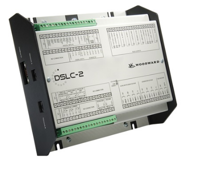
Synchronization Check and Active Synchronization: Real-time calculation of voltage, frequency, and phase differences between two power sources. It supports both slip-frequency synchronization and phase-matching synchronization methods. Before closing the circuit breaker, it automatically verifies voltage matching and issues a close command within the permissible window—enabling “bumpless paralleling.”
Vector Group Adjustment: If the system includes a transformer (e.g., Delta/Wye connection), a fixed phase shift occurs. The LS-521 allows for vector group configuration to provide phase angle compensation, ensuring accurate synchronization assessment.
Mains Decoupling: When installed on the incoming circuit breaker, it automatically detects mains faults (loss of voltage, undervoltage, frequency anomalies, phase shift, rate of change of frequency, etc.). It immediately issues a decoupling command to disconnect the mains side and sends a start signal to the easYgen genset controller, facilitating the automatic switchover from “mains failure” to “generator backup.”
Bus Section Load Control: The power distribution system is divided into multiple segments (up to 32 bus segments) via bus-tie circuit breakers. The LS-521 manages synchronization and load pickup/shedding for its specific segment, transmitting required voltage, frequency, and phase angle reference values to each easYgen unit via the CAN bus to achieve system-wide load sharing.
Operating Modes: Supports AUTO and MANUAL modes. It also supports a “Stand-alone” mode, allowing it to function solely as a synchronization check relay when not connected to an easYgen system.3. Protection Layer: The LS-521 features a comprehensive grid-side protection suite (compliant with ANSI designations): over/undervoltage (59/27), over/underfrequency (81O/U), voltage asymmetry (47), phase shift (78), rate of change of frequency (df/dt or ROCOF, 81), QV monitoring (reactive power/voltage limit violations), time-dependent voltage monitoring, and mains voltage rise protection (per German VDE-AR-N 4105). Additional functions include: circuit breaker trip/close failure detection, synchronization timeout monitoring, voltage plausibility checks, and four freely configurable alarms.
4. Communication Layer
1 CAN bus channel: The system’s “main artery”—a single CAN cable connecting the LS-521 to all easYgen units transmits all AC measurement signals, I/O statuses, and internal flags, significantly reducing internal cabinet wiring;
1 RS-485 channel: For remote control and visualization, enabling integration with SCADA systems;
LogicsManager: Woodward’s soft-logic tool that uses Boolean logic and timers to combine measured values and internal states into custom control and relay functions, allowing for highly customized applications;
Event logging: Stores up to 300 events; includes a battery-backed real-time clock with automatic date and time synchronization between the LS-5 and connected easYgen units; also features circuit breaker operation counters and energy counters.
II. Operation Methods
1. Panel Operation (Local)
Features a graphical LCD display and soft-key operation; includes MAN (Manual), AUTO, and LAMP TEST buttons on the left, and directional navigation keys on the right; supports multiple languages (including Chinese);
Allows viewing of real-time data such as system voltage, frequency, phase difference, power, and synchronization status for both sides;
Includes a keypad lock function to prevent accidental operation; configuration and parameter modifications are password-protected.
2. Role Configuration (Engineer operation via PC or panel) A key feature of the LS-521 is its “one hardware, three roles” design, allowing role switching purely via software: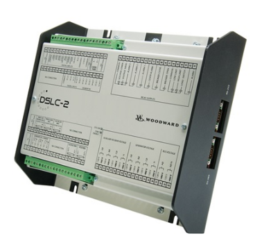
Standalone synchro-check relay (verifies conditions only; does not directly close the breaker);
Mains incomer breaker control (includes mains failure detection, decoupling, and start signal transmission to the easYgen controller);
Bus-tie breaker control (synchronous closing and interconnection between two busbar sections). Full configuration is performed using the ToolKit PC software (connected via DPC cable): selecting the application mode, setting voltage levels (120V/480V), CT ratio (5A nominal), synchronization window (voltage/frequency/phase difference), vector group, protection setpoints and time delays, CAN/RS-485 communication parameters, LogicsManager logic, etc. The series also offers pre-configured application modes, greatly simplifying the setup of complex multi-breaker systems.
3. Remote Operation Enables full remote control via CAN or RS-485 interfaces, including remote close/open commands, mode switching, parameter adjustment, and status visualization; supports integration with power monitoring SCADA systems.
III. Important Notes (Engineer’s Advisory)
Installation and Wiring
Power Supply: DC 12/24V system (supports a wide range of 8–40 VDC); power consumption is approximately 6W. Verify polarity and install appropriate fuses; turn off the charging device before disconnecting or connecting the battery.
Voltage Ranges: The 120V and 480V ranges utilize separate terminal sets. Verify the system voltage level before wiring; incorrect connections will damage the measurement circuitry. Each input features high impedance, but voltage limits must be strictly observed (max. 150V for the 120V range; max. 600V for the 480V range).
CT Circuit: Designed for 5A CTs to match the transformer’s secondary side. Never leave the CT secondary circuit open-circuited; short-circuit the terminals before performing maintenance. Phase assignment and polarity for both measurement systems (System A/B) must be correctly matched; errors here will result in incorrect synchronization logic and power calculations.
Phase Sequence and Polarity: Synchronization logic is highly sensitive to voltage phase sequence and current polarity. Verify these using a phase sequence meter before energizing the system; incorrect phase sequence or polarity is the most common cause of accidents during paralleling operations. Commissioning and Operation
Initial commissioning must strictly follow a step-by-step verification process: “no-load test run → synchronization check only → manual closing → automatic closing.” Each synchronization window and protection action must be confirmed through actual measurement;
The synchronization closing window must be set according to the actual circuit breaker closing time; an excessively wide window causes shock during paralleling, while an excessively narrow window leads to frequent closing failures;
When isolation transformers are present, correct vector group compensation must be configured to avoid phase detection errors;
Mains decoupling tests must be conducted only when a reliable power source is guaranteed for the downstream load (a dedicated Mains Decoupling “Test” mode is available).
Operation and Maintenance
Environment: Operating temperature -20 to +70°C, storage -30 to +80°C, humidity ≤95% (non-condensing); front panel rating IP66/IP54 depending on the mounting method;
Periodically review event logs and closing counters to monitor synchronization performance; when replacing spare parts, verify the order number and software version (ensuring compatibility with the easYgen version requirements).
IV. Application Areas
Independent synchronization check (prevention of incorrect paralleling operations): Acts as a synchronization check relay to prevent operators from accidentally closing the circuit breaker when conditions are not met;
Utility incomer circuit breaker control / AMF (Automatic Mains Failure) switching: Works with easYgen-3400XT/3500XT genset controllers to enable automatic disconnection upon utility failure, automatic generator takeover, and automatic reconnection upon utility restoration; suitable for facilities requiring uninterrupted power supply, such as hospitals, data centers, airports, and financial institutions;
Bus-tie circuit breaker control: Manages interconnection, sectionalized operation, and load transfer between two or more busbar sections; used for power distribution in large industrial complexes and business parks;
Complex power management systems: Supports complex configurations involving multiple utility incomers, bus-tie breakers, and generator breakers; enables system-wide automatic power management with networking capabilities for up to 16 LS-5 units, 32 easYgen-3400XT/3500XT units, and 32 busbar sections;
Grid-parallel applications in Germany and Europe: Complies with VDE-AR-N 4105 / BDEW grid code requirements; used for protection at the point of common coupling (PCC) for distributed energy resources;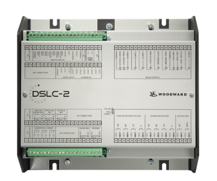
Import/Export control: Works with the genset system to control purchased/exported power, enabling demand management and peak shaving.V. Key Benefits
Transforms “impact synchronization” into “seamless closing”: Triple synchronization checks (voltage, frequency, and phase) combined with active synchronization adjustment eliminate the risk of closing under faulty conditions, thereby protecting generators, transformers, and circuit breakers.
Replaces “manual judgment” with “automated safety”: Features automatic decoupling upon grid failure and automatic start-signal generation; enables unattended power switching to minimize losses during outages.
Simplifies “complex wiring” to a “single cable”: Uses a single CAN bus to transmit all signals between LS-5 units and easYgen controllers, saving panel builders time and costs on wiring, cabinet space, and commissioning.
One hardware platform, multiple roles: Software-based switching between synchronization check, incoming feeder control, and bus-tie control; simplifies spare parts inventory and enhances OEM standardization.
Meets grid requirements: Built-in protections for ROCOF, phase shift, and mains overvoltage; compliant with grid codes in Germany and many other countries, ensuring hassle-free grid connection.
Scalable and customizable: Supports up to 32 busbar segments and 16 LS-5 units; features LogicsManager for flexible logic programming and CAN/RS-485 remote monitoring; covers applications ranging from small ATS setups to large-scale, multi-feeder power management systems. Woodward GmbH
Model recommendation:
EASYGEN 3500XT 8440-2085
8440-1800
8440-1925
8440-1934
8440-1546
8440-1894
8440-2096
8440-2077
WOODWARD 8440-1809
8440-2050
8440-1878
8440-2050
9907-1228-CPC
9907-205
9907-018
9907-163
9907-163
9907-175
9907-149
9907-162
9907-164
9907-165
5466-409
5448-890
8440-2047
SPM-D11 8440-1703
SPM-D11 8440-1706
5463-375
5463-384
8271-147
8271-872
5463-397
More……

admin –
1. Core Functions and Technical Positioning
Speed Control and Electro-hydraulic Control: As a speed governor/electro-hydraulic converter, it supports precise speed control of gas turbines, steam turbines, and diesel generator sets (accuracy ≤ ±0.1%), automatically adapting to 50/60Hz power grid frequency, with a response time ≤ 10ms (emergency stop signal).
Protection and Logic Control: Integrates overload, short circuit, overvoltage/undervoltage, overfrequency/underfrequency, and high temperature protection strategies. Supports programmable logic (such as PID, feedforward control), enabling independent implementation of complex logic control or integration with SCADA/PLC systems.
Communication Capabilities: Equipped with RS485 (Modbus RTU), Ethernet (Modbus TCP/Profibus DP optional), and USB 2.0 programming interfaces, supporting remote configuration (via Woodward ProAct™ software) and parallel control of multiple units (up to 248 units).
2. Specifications and Expandability
Electrical Parameters: Operating voltage 24VDC (±10%), power consumption ≤30W; Input supports 8 channels of analog signals (4-20mA/0-10V), 16 channels of digital signals (dry/wet contacts); Output includes 8 channels of analog signals (4-20mA, load ≤500Ω), 8 channels of relay output (10A/250VAC), and PWM fuel valve control (5-20kHz).
Mechanical and Environmental Specifications: Dimensions 210mm × 180mm × 75mm, weight approximately 2.5kg, protection rating IP20 (standard)/IP65 (optional); operating temperature -20℃ to 70℃, suitable for extreme environments such as outdoor and offshore platforms.
Expansion Modules: Compatible with AnalogManager expansion board (adds analog channels), digital I/O module (expands to 32 input/output points), engine ECU communication module (supports SAE-J1939 protocol), and redundant power supply module.
3. Application Scenarios and Compatibility
Core Applications: Parallel control of generator sets, distributed generation, microgrids, emergency backup power, combined heat and power (CHP), and biogas power generation scenarios. It can collaborate with main controllers such as the EasyGen 3500XT (8440-2085) to achieve load sharing and automatic start/stop of multiple generator sets.
Industry Compatibility: Widely used in data centers, hospitals, commercial facilities, oil and gas exploration, wastewater treatment, and independent power supply systems for mobile equipment (such as leased generators).
Summary: As a representative of Woodward’s industrial control modules, the 8440-1947, with its high-precision speed regulation, strong protection logic, and multi-protocol communication capabilities, has become a core solution for generator set control. It is suitable for complex needs ranging from single-unit control to multi-unit parallel operation, while also supporting remote monitoring and intelligent operation and maintenance. It is a key component for industrial-grade generator set control.
https://www.weikunfadacai1.com/product/woodward-8440-1947/
admin –
Model Name: Woodward 8440-1947
Platform Classification: LS-5 Series (LS-521 Synchronous Parallel Integrated Controller), originally classified as a generator set synchronous/parallel integrated controller (Generator set synchronizer & load sharing controller) MOORE AUTO… Origin: Original Woodward, USA
Aliases: Synchronous relay, parallel controller, generator power management unit
Installation Method: Panel-mounted embedded installation
II. Core Positioning
Integrates automatic synchronization, load sharing among multiple generator sets, mains/generator switching, complete relay protection, and integrated engine start/stop control. Suitable for diesel/gas generator sets, distributed microgrids, combined heat and power, backup power stations, offshore platform power supplies, and single or multiple unit parallel operation scenarios.
III. Core Functions
1. Synchronization and Grid Connection Core (Main Function)
Automatic capture of frequency difference, phase difference, and voltage difference; soft synchronization closing via frequency sliding.
Supports unit parallel operation, unit grid connection to the mains, and multi-bus islanding operation.
Automatic soft load transfer, disconnection, and reverse power protection tripping.
Peer-to-peer parallel operation, supporting up to 32 units in parallel to evenly distribute active/reactive loads.
2. Complete Unit Logic Control
Fully automatic engine start, stop, preheating, and idle speed switching.
Speed/voltage regulation bias output, interface with engine ECU and AVR excitation regulator.
Local manual/automatic mode switching (MAN/AUTO panel buttons), lamp self-test.
3. Comprehensive Electrical + Mechanical Protection
Electrical protection: overcurrent, overload, reverse power, overvoltage/undervoltage, overfrequency/ Underfrequency, phase sequence fault, differential protection
Engine protection: high temperature, low oil pressure, overspeed, cylinder temperature over-limit, emergency stop interlock
Fault record storage, historical alarm query, multi-level password parameter locking
4. Signal and IO capabilities
Analog input: 4–20mA / 0–10V dual compatibility, True RMS sampling, harmonic interference suppression
Digital DI: 16-channel switch input; DO: 8-channel C-type relay output (5A/250VAC)
Measurement accuracy: 0.5-level electrical quantity acquisition (voltage, current, active power, reactive power, power factor, frequency)
IV. Hardware Electrical Specifications
Table
Item Parameters
Power supply: 12/24 VDC wide range (8–32VDC), total power consumption ≤5W
AC sampling: 250VAC, 50/60Hz (40–85Hz wide range), 5A Current Transformer Input
Operating Temperature: -20℃ ~ +70℃; Storage Temperature: -40℃ ~ +85℃
Ambient Humidity: 95% RH, non-condensing
Dimensions: 219×171×61mm; Net Weight: 0.85kg
Insulation Withstand Voltage: 300VAC (Phase-to-Ground)
V. Communication Interfaces
CAN Bus: Supports SAE J1939, direct connection to diesel/gas engine ECU, reading speed, water temperature, and oil pressure
RS485 Modbus RTU: Interfacing with upper-level PLC and SCADA monitoring systems
Optional Ethernet Modbus TCP expansion for remote cloud monitoring and parameter download
Supporting Debugging Software: OpView/easYgen debugging and configuration tools
VI. Typical Application Scenarios
Data Centers, Hospitals, Commercial Complex Backup Diesel Power Stations
Natural Gas Distributed Cogeneration (CHP) Units
Offshore Drilling Platforms, Marine Auxiliary Generator Sets
Industrial Park Off-Grid Microgrids, Photovoltaic Power Plants + Energy Storage + Diesel-Generator Hybrid System
Municipal emergency power supply, large-scale diesel power station with multiple units operating in parallel
https://www.weikunfadacai1.com/product/woodward-8440-1947/
admin –
Signal Processing Capabilities: Supports dual-mode input of current (4-20mA) and voltage (0-5/10V), employing true RMS detection technology to reduce harmonic interference; 12-bit resolution, sampling period as low as 50ms.
Parallel and Islanded Operation: Supports peer-to-peer parallel operation, mains parallel operation, multiple mains parallel operation, and islanded mode, suitable for distributed generation, microgrids, and combined heat and power (CHP) scenarios.
Communication and Integration:
Built-in CAN network interface, supporting SAE-J1939 protocol and engine OEM proprietary protocol, enabling real-time communication with the engine ECU.
admin –
Environmental Adaptability: Complies with CE, UL/cUL, CSA, BDEW, ABS, Lloyd’s Register certification standards, and meets international standards such as ISO 8528 and IEC 60034. Protection ratings range from IP20 to IP67 depending on the application scenario, with electromagnetic interference (EMC) immunity and an operating temperature range of -20℃ to 60℃.
Core Parameters and Technical Characteristics
Signal Processing Capabilities: Supports dual-mode input of current (4-20mA) and voltage (0-5/10V), employing true RMS detection technology to reduce harmonic interference; 12-bit resolution, sampling period as low as 50ms.
Parallel and Islanded Operation: Supports peer-to-peer parallel operation, mains parallel operation, multiple mains parallel operation, and islanded mode, suitable for distributed generation, microgrids, and combined heat and power (CHP) scenarios.