
Description
IS420ESWBH1A – 16 ports Ethernet IONet Switch 10/100Base-TX is available in stock which ships the same day.
IS420ESWBH1A – 16 ports Ethernet IONet Switch 10/100Base-TX comes in UNUSED as well as REBUILT condition.
To avail our best deals for IS420ESWBH1A – 16 ports Ethernet IONet Switch 10/100Base-TX, contact us and we will get back to you within 24 hours.
IS420ESWBH1A Alternative Names:
IS420ESWBH1A Ethernet Switch
IS420ESWBH1A Communication Unit
IS420ESWBH1A Analog Unit
IS420ESWBH1A IONet Switch. This switch was part of the Mark VIe series and has sixteen 10/100Base-TX copper ports with only one multi-mode 100Base-FX fiber port. The IS420ESWBH1A switch can be used in parallel or perpendicular mounting options with a BVP1 or BVP4 clip.
I. Operating Principle
The IS420ESWBH1A utilizes a store-and-forward switching architecture, featuring an integrated 256KB packet buffer and a 4K MAC address table. It complies with IEEE 802.3, IEEE 802.3u, and IEEE 802.3x Ethernet standards, is compatible with the proprietary GE IONet real-time control network, and prioritizes the forwarding of time-sensitive EGD (Ethernet Global Data) control packets.
The hardware ports support 10/100 Mbps auto-negotiation and full/half-duplex auto-adaptation. With integrated HP-MDIX automatic cable detection, the device automatically adapts to both straight-through and crossover cables without requiring manual wiring adjustments.
Upon receiving data packets from controllers or I/O modules, the device verifies frame integrity, consults the MAC address table, and forwards packets to the appropriate destination port. It includes a built-in broadcast storm suppression mechanism that automatically limits traffic during abnormal broadcast surges, preventing control network paralysis and ensuring the prioritized transmission of critical commands such as trips and emergency stops.
The unit is equipped with dual DC redundant power inputs (utilizing a diode OR-gate circuit) for independent power supply, ensuring continuous operation even if one power source fails. As an unmanaged switch, it operates without an operating system or IP configuration requirements—booting up immediately upon power-up—and does not support remote login for parameter modification.
Hardware interfaces include sixteen 10/100Base-TX RJ45 copper ports and one 100Base-FX multimode fiber-optic uplink port (LC connector). The copper ports facilitate short-range I/O module networking within the cabinet, while the fiber-optic port enables interference-resistant network extension across cabinets or over long distances, allowing for the configuration of star or ring IONet topologies.
II. Core Product Advantages
Native System Adaptation & Real-Time Performance: Designed specifically for the GE Mark VIe turbine control system—rather than being a standard commercial IT switch—it features packet forwarding latency strictly aligned with the closed-loop control requirements of gas turbines. It ensures clock synchronization across multiple I/O nodes and deterministic transmission of control signals, eliminating control instability caused by the random latency typical of standard switches.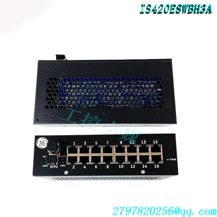
Redundant Power & High-Reliability Industrial Hardware: Features dual 18–36VDC redundant power inputs and a soft-start design to minimize inrush current during power-up. Built with wide-temperature industrial-grade hardware and a metal housing, it supports DIN-rail or panel mounting. It offers resistance to vibration and electromagnetic interference (EMI) and boasts a high MTBF, meeting the demands of continuous, long-term operation in power plants.
Plug-and-Play (No Configuration Required) & Reduced O&M Risk: An unmanaged architecture requiring no complex network parameter settings; it operates automatically upon power-up, eliminating downtime risks associated with human configuration errors. All ports feature HP-MDIX auto-sensing, simplifying on-site wiring.
Mixed-Media Networking Capability: Provides both RJ45 copper ports and multimode fiber-optic uplink ports, accommodating short-range internal cabinet wiring as well as long-distance fiber communication in high-EMI environments, allowing for flexible IONet topology configuration.
Built-in Network Protection Mechanisms: Includes broadcast storm suppression and traffic buffering capabilities to suppress abnormal traffic from faulty I/O nodes, isolate network faults, and prevent a single point of failure from propagating across the entire turbine control network.
III. Target Industries & System Role
Applicable Industries
Primarily used in thermal power plants, gas turbine combined-cycle (GTCC) power plants, combined heat and power (CHP) facilities, and oil & gas power stations; also suitable for large industrial drive turbine units and Mark VIe automation control systems for power plant auxiliary equipment.Role in the Control System
IONet Control Network Backbone Forwarding Unit: Acts as the hub for the Mark VIe system’s internal I/O network, enabling high-speed, bidirectional, real-time data exchange among the main controller, remote I/O modules, and terminal boards. It transmits process variables, valve position commands, protection trip signals, and status feedback data.
Signal Isolation and Network Expansion: Uses fiber-optic ports to isolate electrical interference and extend IONet communication distances. It connects geographically dispersed I/O stations to a single turbine control system, establishing a distributed control network.
Ensuring Reliable Communication for Unit Protection Loops: Interlock protection signals—such as those for overspeed, over-temperature, and vibration—are transmitted via the IONet switch. Stable network forwarding provides the hardware foundation for the proper execution of gas/steam turbine protection logic and is directly critical to the safety of the power equipment.
System Expansion and Topology Configuration: Multiple IS420ESWBH1A units can be cascaded to increase the number of IONet network nodes. It supports star or redundant ring network architectures, meeting the requirements for multi-module distributed I/O expansion in large power plants.
IV. Standard Operating Procedures
Caution: All operations must be performed while the equipment is powered off and the unit is under a maintenance permit. Hot-plugging fiber-optic cables or RJ45 control cables while the device is powered on is strictly prohibited.
Installation and Mounting: Select a well-ventilated location within the control cabinet. Secure the unit to the DIN rail using the GE-supplied DIN rail clip or mount it to the panel using screws. Leave sufficient clearance around the device to ensure natural convection cooling; do not enclose it in a sealed housing.
Power Wiring: Connect two independent 18–36 VDC power sources, ensuring correct polarity. Establish a protective ground connection by connecting the switch’s grounding terminal to the cabinet’s protective earth to minimize electromagnetic interference. The two power sources operate independently to provide redundancy. Communication Cable Connection
RJ45 Copper Port: Use an industrial shielded network cable; connect one end to the switch’s RJ45 port and the other to the network port of the Mark VIe controller or distributed I/O module. There is no need to distinguish between straight-through and crossover cables.
Fiber Optic Port: Use an LC multimode fiber patch cord. After cleaning the fiber end-face, insert it into the switch’s LC optical port and connect the other end to the optical port of the remote IONet switch. Observe the minimum fiber bend radius to avoid excessive bending.
Power-up and Status Check: After verifying the wiring, apply power to both power supply inputs. Observe the panel indicator lights: a steady power light indicates normal power supply; a steady Link light indicates an established link, while a flashing light indicates data transmission/reception. Record the I/O station corresponding to each port.
Shutdown and Removal: First, disconnect the power and wait for the device to power down. Unplug the network cables and fiber optics in sequence, then remove the switch from the DIN rail. Immediately place dust caps on the fiber end-faces to prevent contamination.
System Verification: After powering up the switch, check the IONet network status using the Mark VIe ToolboxST software. Confirm that all I/O nodes are communicating normally, with no packet loss or link alarms, before placing the unit into operation.
V. Important Precautions
System Compatibility Limitations: The IS420ESWBH1A is designed exclusively for GE Mark VIe / Mark VIeS IONet control networks and must not be used as a standard office network switch. When replacing or adding this switch, ensure the control system firmware version matches and verify hardware/software compatibility in ToolboxST beforehand. Environmental Requirements: The device relies on natural convection for heat dissipation; do not block the ventilation openings. Avoid installation in areas characterized by high temperatures, humidity, condensation, heavy dust, or highly corrosive gases. Maintain a condensation-free operating environment to prevent metal terminals from oxidizing and short-circuiting.
Cable and Fiber Optic Maintenance: Shielded industrial Ethernet cables are preferred. Route cables inside the cabinet away from power cables and variable frequency drive (VFD) cables to minimize EMI interference. Do not touch fiber optic end-faces; if contaminated, clean them using specialized fiber optic cleaning wipes, as dirt can cause packet loss and communication interruptions on the optical link.
Grounding Specifications: Grounding must be reliable. Poor grounding introduces common-mode interference, leading to intermittent packet loss and communication jitter on the IONet network, which compromises the control stability of the turbine unit.
Troubleshooting Guidelines: In the event of a port disconnection, first check the power supply, cables, and fiber optic end-faces. As the switch is a non-managed device, it is not possible to log in to view network logs. If the unit’s power indicator is off, inspect the DC power supply circuit. If multiple ports fail simultaneously, focus the investigation on grounding, power supply, and electromagnetic interference.
Safety Critical Rules: Do not plug or unplug IONet Ethernet cables or fiber optics, nor replace the switch while the unit is powered, during normal operation. Since IONet is a critical network for unit protection and control, any network modifications require an approved I&C (Instrumentation and Control) work permit and must be performed while the unit is shut down or isolated.
Spare Parts Storage: Store spare parts in a dry, temperature-controlled environment. Implement dust protection measures for long-term storage, and keep dust caps installed on fiber optic ports to prevent oxidation and damage.
IS420ESWBH1A Manuals, White Papers, Data Sheets, and Troubleshooting
GEH-6725 Manual IS420ESWBH1A Mark VIe and Mark VIeS Controls Equipment HazLoc Manual.pdf
IS420ESWBH1A GEH-6855_Vol_I Mark VIeS Functional Safety Systems Vol I System Guide Manual.pdf
GEH-6855_Vol_II Mark VIeS Functional Safety Systems Manual IS420ESWBH1A.pdf
GEH-6861 Mark VIeS Functional Safety System Equipment in HazLoc IS420ESWBH1A.pdf
IS420ESWBH1A IONet Switches Data Sheet.pdf
Reviews For IS420ESWBH1A
As the first of the ESWB packs, there is only one multi-mode fiber port, but there are sixteen copper ports that are used for a number of different removals and installations. This model has the capability to be used in DIN-rail or panel mounting, but DIN-rail mounting is preferred for proper operation.
Model recommendation:
IS420ESWBH3A GE
IS420ESWBH3A-C GE
IS420ESWBH2A GE
IS420ESWBESWB GE
IS420ESWAH1A GE
IS420ESWBH3A-ESWA GE
IS420ESWAH2A GE
IS420ESWBH3A GE
IS420ESWBH3AE GE
IS420ESWAH3A GE
MARINE PCB ASSY PN-03956-1980732-2-7250209-REV-D MOTHERBOARD
KONGSBERG NORCONTROL HA339587A-ETU-003 ENGINE TELEGRAPH UNIT
JRCS SMS-U950 FSCU UNIT
ROLLS-ROYCE M44I-16-0-ITEM-99588 CIRCUIT BOARD
GE VMIACC-5595-208
REXROTH A27920 VT-MSPA-2-525-10-V0 MNR-0811405106
HONEYWLL CC-PAIH01 51405038-175
HONEYWLL CC-PAIX02 51405038-475
IS41yJPDDG2A
IS41yJPDDG3A
IS40yJPDGH1A
IS411JPDHG1A
IS4210UCSBH4A
more……

admin –
https://www.weikunfadacai1.com/product/is420eswbh1a-ge/
Product Description
The first of the ESWB models the IS420ESWBH1A switch is the second hardware version of the IONet Switch. This switch is made up of sixteen 100/100Base-TX RJ45 copper ports. This switch only has one fiber port which is described as a multi-mode 100Base-FX port with an LC-type connector. The fiber ports are the only distinct difference between the five ESWB models.
As with the previous hardware models for the ESWx switches, the IS420ESWBH1A can also be mounted in various configurations, either parallel or perpendicular, there is a difference between which clips can be used in the perpendicular mounting. The clip used with the ESWB switch in the perpendicular mounting orientation is the 259B2451BVP4 clip. Note that when this switch is being installed as a replacement it can be installed in the DIN-rail or panel mount.
admin –
FUNCTIONAL DESCRIPTION:
IS420ESWBH1A is a 16-port Ethernet IONet Switch 10/100Base-TX manufactured and designed by General Electric as part of the Mark VIe Series used in GE Distributed Control Systems. GE’s Industrial Ethernet 10/100 switches (ESWA and ESWB) provide the performance and features needed in real-time industrial control systems. Use 8-port ESWA or 16-port ESWB Ethernet switches in all control system I/O networks to maintain the reliability needed for I/O module reception of controller outputs.
admin –
Standard Operating Procedures
Caution: All operations must be performed while the equipment is powered off and the unit is under a maintenance permit. Hot-plugging fiber-optic cables or RJ45 control cables while the device is powered on is strictly prohibited.
Installation and Mounting: Select a well-ventilated location within the control cabinet. Secure the unit to the DIN rail using the GE-supplied DIN rail clip or mount it to the panel using screws. Leave sufficient clearance around the device to ensure natural convection cooling; do not enclose it in a sealed housing.
Power Wiring: Connect two independent 18–36 VDC power sources, ensuring correct polarity. Establish a protective ground connection by connecting the switch’s grounding terminal to the cabinet’s protective earth to minimize electromagnetic interference. The two power sources operate independently to provide redundancy. Communication Cable Connection
RJ45 Copper Port: Use an industrial shielded network cable; connect one end to the switch’s RJ45 port and the other to the network port of the Mark VIe controller or distributed I/O module. There is no need to distinguish between straight-through and crossover cables.
Fiber Optic Port: Use an LC multimode fiber patch cord. After cleaning the fiber end-face, insert it into the switch’s LC optical port and connect the other end to the optical port of the remote IONet switch. Observe the minimum fiber bend radius to avoid excessive bending.
Power-up and Status Check: After verifying the wiring, apply power to both power supply inputs. Observe the panel indicator lights: a steady power light indicates normal power supply; a steady Link light indicates an established link, while a flashing light indicates data transmission/reception. Record the I/O station corresponding to each port.
Shutdown and Removal: First, disconnect the power and wait for the device to power down. Unplug the network cables and fiber optics in sequence, then remove the switch from the DIN rail. Immediately place dust caps on the fiber end-faces to prevent contamination.
System Verification: After powering up the switch, check the IONet network status using the Mark VIe ToolboxST software. Confirm that all I/O nodes are communicating normally, with no packet loss or link alarms, before placing the unit into operation.