
Description
Many products have not yet been listed online; please contact us for more information.
If the product model differs from the displayed image, the model number takes precedence. Please contact us for specific product photos; we can arrange for warehouse staff to take and send confirmation images.
We operate 76 shared warehouses globally; consequently, it may sometimes take a few hours to provide an accurate response. We appreciate your understanding. Rest assured, we will address your inquiries as quickly as possible.
I. Product Overview
The IS420ESWBH3A is an industrial-grade unmanaged Ethernet switch designed by General Electric (GE, now GE Vernova) specifically for the Mark VIe and Mark VIeS safety control systems. It serves as a core communication device for the IONet (I/O Network). This model is the copper-cable-only version of the ESWB series, featuring sixteen 10/100Base-TX RJ-45 electrical ports (with no fiber-optic interfaces). It is primarily used to establish deterministic, real-time field I/O data exchange networks within gas turbines, steam turbines, and integrated power generation control systems.
As one of the three key hardware components of the Mark VIe control architecture (alongside controllers and I/O modules), the IS420ESWBH3A is an essential component for all Mark VIe/Mark VIeS systems utilizing the IONet protocol. It is currently in the “Active” lifecycle stage and serves as a direct replacement for spare parts of the same model.
II. Operating Principle
2.1 Network Positioning
The IS420ESWBH3A operates at Layer 2 (Data Link Layer) of the OSI model and utilizes the Store-and-Forward switching mechanism. It does not participate in control logic operations but instead serves as a “data traffic hub,” connecting Mark VIe main controllers (such as UCSB, UCSC, and UCDH processor modules) with various field-side I/O terminal boards (e.g., SRTD/STTC temperature acquisition boards, STPD pressure boards, and DI/DO discrete I/O boards) within the same logical network. This enables high-speed, bidirectional forwarding of control commands (downstream) and field data (upstream).
2.2 IONet Protocol and EGD Data Exchange
IONet is GE’s proprietary, full-duplex, deterministic industrial Ethernet protocol. Operating at 100 Mbps, it is specifically designed for the transmission of real-time control data with millisecond-level latency. The IS420ESWBH3A natively supports this protocol and utilizes the EGD (Ethernet Global Data) mechanism to exchange multicast UDP data packets between controllers and I/O nodes in a periodic and deterministic manner.
Unlike standard commercial switches, this device features at least 256 KB of data buffering and a 4K MAC address table. It can centrally buffer multicast and broadcast packets, effectively handling high-frequency multicast traffic on the IONet network without the frame collisions typical of unmanaged switches. This ensures communication determinism for critical control loops, such as turbine speed regulation, fuel valve servo control, and overspeed protection.
2.3 Protocol Compatibility
In addition to GE’s proprietary IONet/EGD protocols, the IS420ESWBH3A is fully compatible with IEEE 802.3, 802.3u, and 802.3x standards. It supports 10/100 Mbps auto-sensing, full-duplex/half-duplex auto-negotiation, and HP-MDIX (automatic polarity crossover) functionality. It simultaneously handles Modbus TCP supervisory communication traffic and IEEE 1588 precision time synchronization packets, enabling the Mark VIe system to exchange data with third-party equipment such as plant-wide DCS, OPC servers, excitation systems (EX2100e), and Load Commutated Inverters (LCI).
2.4 Redundant Power Supply Principle
The device is equipped with two independent power input terminal blocks (TB1 and TB2); the two 24/28 VDC power sources are connected in parallel via a Diode-OR circuit. If one power source fails, the other automatically and seamlessly takes over, allowing the switch to operate without interruption and meeting the control system’s stringent requirements for communication link availability.
III. Technical Advantages
1. Industrial-grade wide-temperature design: Supports an operating temperature range of -40°C to +70°C and a storage temperature range of -40°C to +85°C. It utilizes fanless convection cooling—eliminating fan wear, a common point of failure—enabling long-term operation in harsh environments such as power plant turbine halls and outdoor oil platforms.
2. Comprehensive hazardous area certifications: Certified for Class 1, Division 2 / Class 2, Zone 2 / ATEX hazardous locations. It features a “non-interfering” protection rating and meets ISA-S71.04 G3 corrosion resistance standards, making it suitable for oil & gas, chemical, and other facilities exposed to corrosive gases and flammable or explosive media.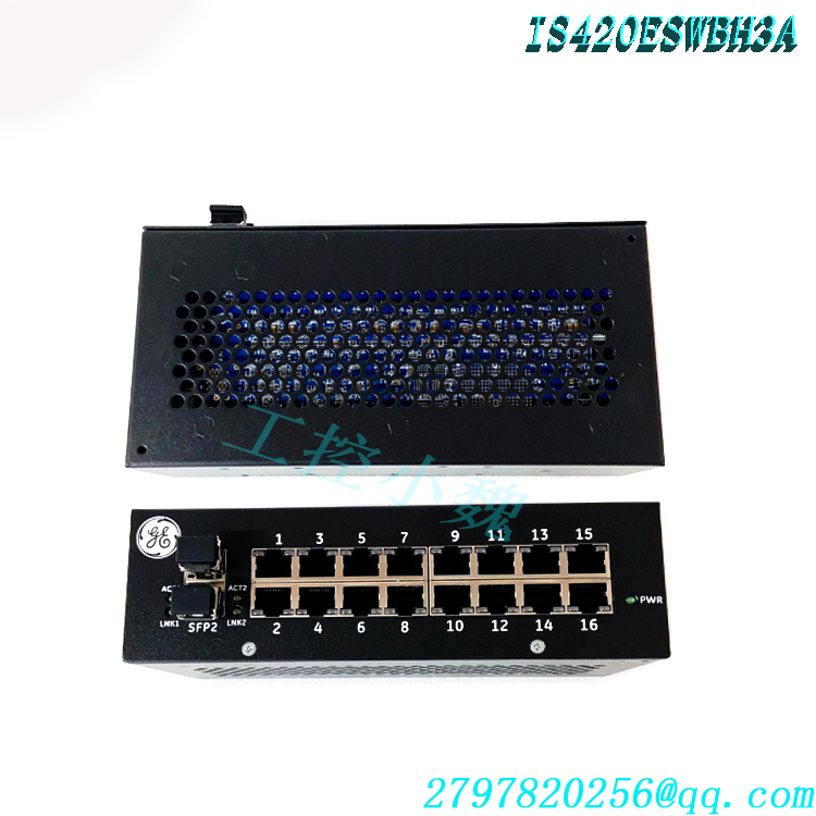
3. Hardware power redundancy: Features dual 24/28 VDC Diode-OR redundant power supplies; a single power supply failure does not interrupt communication, ensuring control network availability at the hardware level. 4. Plug-and-play, configuration-free: As an unmanaged switch, it requires no configuration of parameters such as IP addresses, VLANs, or Spanning Tree protocols via a console port or web interface. It operates immediately upon power-up, significantly reducing on-site commissioning time and eliminating the risk of communication failures caused by configuration errors.
5. Automatic polarity detection: The HP-MDIX auto-crossover function eliminates the need to distinguish between straight-through and crossover cables during on-site wiring, thereby reducing the likelihood of incorrect connections during installation.
6. High-density 16-port design: A single unit provides 16 RJ-45 copper ports, allowing for the connection of more I/O terminal boards within the same installation footprint; compared to the 8-port ESWA model, this reduces the number of switches required and minimizes cabinet space usage.
7. Comprehensive status indication: Each port is equipped with a dual-color LED indicating link status, data activity, duplex mode, and speed. A separate power status indicator on the front panel allows operations and maintenance personnel to quickly assess port and power status without connecting diagnostic software.
8. Compact size and flexible installation: With dimensions of only 18.8 × 8.6 × 5.6 cm, the unit supports standard DIN-rail mounting. Depending on available space, it can be installed with its long edge either parallel or perpendicular to the rail.
IV. Applications Across Industries
4.1 Gas-fired and Combined-Cycle Power Plants
The IS420ESWBH3A is most typically applied in the Mark VIe control networks for GE 7FA, 9FA, 6FA, 6B, and H-class heavy-duty gas turbines, as well as aeroderivative gas turbines. It handles the real-time transmission of fuel valve servo control commands, combustion chamber temperature monitoring data, vibration monitoring signals, and Combustion Pulsation Monitoring (CPM) data packets between the controller and field I/O; it serves as the communication foundation ensuring the proper execution of unit start/stop sequences, load regulation, and overspeed protection functions.
4.2 Steam Turbine Power Plants
In steam turbine-generator units, this switch connects I/O signals such as main steam/control valve position feedback, bypass system control, extraction steam regulation, and condenser vacuum monitoring, supporting the rapid response of the steam turbine’s Digital Electro-Hydraulic (DEH) control system and protection system.
4.3 Oil and Gas Industry
It is applied in anti-surge control and load-sharing systems for turbocompressors in long-distance natural gas pipeline compressor units, offshore drilling platforms, and Floating Production, Storage, and Offloading (FPSO) vessels. With Class 1 Div 2 / ATEX hazardous area certifications and G3 corrosion resistance, it can be installed directly at the edge of explosion-proof zones and in environments containing salt mist or hydrogen sulfide.
4.4 Nuclear and New Energy
The Mark VIe platform extends widely into control systems for nuclear power conventional islands, wind turbine generators, photovoltaic (PV) farm step-up substations, and hydroelectric plant monitoring systems. Acting as an IONet network switching node, the IS420ESWBH3A consolidates unit-level real-time control data in these applications and facilitates data upload to the plant-level Distributed Control System (DCS) via Modbus TCP or OPC UA.4.5 Chemical Industry, Seawater Desalination, and Industrial Process Control
In control systems for gasification units, seawater desalination plants, and large-scale plant Balance of Plant (BoP) facilities, this switch is used to construct distributed I/O networks. It aggregates data from remote field devices to the central controller while serving as an isolation boundary between the field network and the upper-level management network.
V. Installation and Operation
5.1 Pre-installation Preparation
Verify that the power supply is 24 VDC or 28 VDC; the two power inputs must originate from independent power circuits.
Prepare Cat 5e UTP cables compliant with the T568B standard, using RJ-45 (8P8C) connectors; the transmission distance for a single copper cable segment must not exceed 100 meters.
Select the appropriate GE-certified DIN rail mounting bracket based on the installation orientation: use model 259B2451BVP1 if the long side is parallel to the rail, or model 259B2451BVP4 if the long side is perpendicular to the rail (brackets are ordered separately; mounting screws are included).
5.2 Mechanical Installation Steps
Attach the selected mounting bracket to the bottom of the device.
Hook the device bracket onto the standard DIN rail and ensure it is securely locked in place.
For panel mounting, the device can be secured directly to the mounting plate using the included screws.
Ensure sufficient space for natural convection ventilation around the device; do not stack debris above or below the unit.
5.3 Electrical Wiring
Connect the positive and negative terminals of the first 24/28 VDC power supply to terminal block TB1 (Phoenix Contact MC 1.5/S-STF-3.81; two connectors are included).
Connect the second (redundant) power supply to the corresponding terminals on TB2.
Verify the correct power supply polarity before applying power; the power LED on the front panel should light up.
5.4 Network Wiring and Operation
Connect the IONet port of the Mark VIe main controller (UCSB/UCSC/UCDH) to any RJ-45 port using a Cat 5e network cable.
Connect the field I/O terminal boards (e.g., TBIO or TBSM series) to the remaining ports.
For each port with a valid link, the corresponding LED should be either steadily lit or flashing (flashing indicates data transmission/reception).
The device is unmanaged and requires no software configuration; IONet communication is established automatically upon power-up. The status of each I/O node can be verified at the controller using the Mark VIe ToolboxST software.
5.5 Spare Part Replacement
If the device fails and requires replacement, it can be directly swapped with an identical IS420ESWBH3A unit (the replacement part number matches the original model number). No changes to network wiring or controller configuration are required, ensuring minimal downtime.
VI. Precautions for Use
1. Model Identification: The suffixes H1A through H5A in the ESWB series correspond to different fiber-optic configurations; the H3A model is a copper-only version with no fiber-optic ports.
1. Ordering and Replacement: When ordering or replacing the unit, strictly verify the full model number (IS420ESWBH3A) to avoid purchasing the fiber-optic port version by mistake, which would result in incompatible wiring connections.
2. Power Supply Requirements: The input voltage must be strictly maintained within the 24/28 VDC range; connection to AC power or DC voltage exceeding the rated value is prohibited. It is recommended that the two power sources originate from different UPS units or separate power buses to ensure true redundancy.
3. Wiring Specifications: Use Cat 5e (or higher) shielded or unshielded twisted-pair cables. Network cables must be routed separately from power cables—avoiding parallel runs in the same conduit or tray—to minimize electromagnetic interference affecting 100 Mbps real-time data transmission.
4. Heat Dissipation and Environment: Although the unit features a fanless design, the installation location must maintain an ambient temperature between -40°C and +70°C. The environment must be free of corrosive contaminants exceeding G3 severity levels, and no objects should be stacked above the device that might obstruct ventilation.
5. Grounding and Lightning Protection: For outdoor or long-distance cabling, ensure the cabinet is properly grounded. If necessary, install signal surge protectors on the network cable links to prevent voltage surges from entering the switch ports via the cables.
6. Live Operation Restrictions: While RJ-45 ports support hot-swapping, the power terminals (TB1/TB2) must only be connected or disconnected while the power is off; it is recommended to disconnect both power sources before replacing the device.
7. Troubleshooting Approach: If a port LED fails to light up, first check the network cable, the power status of the connected device, and the quality of the RJ-45 connector crimping. If the power LED fails to light up, measure the voltage at terminals TB1 and TB2 to determine whether the issue lies with the power supply circuit or the device itself. As there are no device configurations to check, the vast majority of communication anomalies originate at the physical layer (cables, connectors, or remote-end modules).
8. Certification Usage Boundaries: The device’s Class 1 Div 2 / ATEX certification applies only to the specified hazardous area classifications; the installation environment rating must not be altered without authorization. For specific installation details regarding hazardous areas, refer to GEH-6861, Mark VIeS Functional Safety System Hazardous Area Equipment Guide.
Related product recommendations:
IS420UCSCH1A-B
IS420UCSCH1A-F-VO.1-A
IS420YAICS1B
IS420UCSBH4A
IS420UCSBH1A
IS420UCSCS2A-B-V0.1-A
IS420PVIBH1B
IS420ESWBH4A
IS420ESWBH5A
IS420ESWAH5A
IS420UCSCH1B
IS220YDIAS1A
IS200AEPAH1BKE
IS200TDBSH2ACC
IS220PRTDH1A
IS220PSCAH1A
IS220PVIBH1A
IS200JPDEG1A
IS200VPROH1BEF
IS200VPROH2B
More……

admin –
Role in the System
In the Mark VIe control architecture, controllers (such as UCSB, UCSC, and UCDH modules) and field-distributed I/O modules (IS230/IS420 series) are interconnected via the IONet real-time network. IONet is a deterministic network based on Industrial Ethernet that supports the EGD (Ethernet Global Data) protocol for high-speed, periodic data exchange:
The IS420ESWBH3A functions as a “Level 1” network switch, networking controllers, I/O packs, and cabinet-internal devices within the same node into a single IONet segment;
The system is designed with dual IONet redundancy (IONet A and IONet B); two independent switch networks operate simultaneously, ensuring that a failure in either network or a single device does not disrupt control communications;
It is engineered to handle the high-frequency UDP multicast traffic characteristic of IONet, preventing the frame collisions common in standard unmanaged switches and ensuring the integrity of EGD packets during transient turbine operating conditions. dcscontroller.com / ManualsLib
Hardware and Electrical Specifications
Based on the GE Mark VIe system manual and product documentation, the key specifications are as follows:
Port Configuration: 16 x 10/100Base-TX copper RJ-45 ports (auto-negotiation, Auto-MDIX); this model features copper ports only and lacks fiber-optic ports (for applications requiring fiber uplinks, please select the ESWA series models equipped with fiber ports);
Switch Type: Layer 2 unmanaged industrial switch; store-and-forward switching mode; plug-and-play (no configuration required);
Power Supply: Supports redundant DC power inputs; rated 24/28 VDC (operating range: 18–36 VDC; corresponds to the 200/400 mA dual-power interface design in the GE manual); dual power inputs utilize diode-based “OR” logic, ensuring continuous operation even if one power source fails;
Operating Temperature: -40°C to +70°C (compliant with industrial standards; capable of withstanding high-temperature environments within power plant cabinets);
Mounting: DIN-rail mounting (panel mounting also supported); compact design; passive cooling via natural convection;
Status Indicators: Front-panel LEDs for port status, power, etc., facilitating on-site inspections;
Physical Dimensions: Compact metal-cased module, approximately 18.8 cm (H) x 8.6 cm (W) x 5.6 cm (D).