
Description
Many products have not yet been listed online; please contact us for more information.
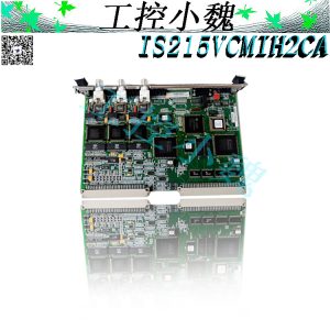
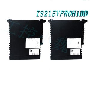
If there is a discrepancy between the product model and the displayed image, the model number takes precedence. Please contact us for specific product photos; we can arrange for warehouse staff to take and provide confirmation images.
We operate 76 shared warehouses globally; consequently, it may sometimes take a few hours to provide you with an accurate response. We appreciate your understanding. Rest assured, we will address your inquiries as quickly as possible.
I. Product Overview
The 151X1207BB53SA01 is an ASM-EX series blower cooling module developed by General Electric (GE) specifically for the EX2100 series excitation control system; it serves as a core thermal management component of the excitation system. Custom-designed to match the structural layout and heat generation characteristics of the EX2100 excitation cabinet, this module provides forced-air cooling for high-heat components—such as the Power Conversion Module (PCM), thyristor rectifier bridge, excitation regulator board, and excitation transformer. It is a critical auxiliary unit that ensures the long-term, stable operation of the excitation system and prevents shutdowns caused by overheating. It is fully compatible with the entire EX2100 and EX2100e series of excitation control cabinets.
II. Working Principle
2.1 Core Heat Exchange Logic
During the operation of the excitation system, power electronic components (such as IGBTs, thyristors, and power resistors) continuously generate significant Joule heat. Heat accumulation can lead to component parameter drift, accelerated insulation aging, and even system shutdowns triggered by overheat protection mechanisms. Based on the principle of forced convection heat transfer, the 151X1207BB53SA01 blower module utilizes a motor-driven centrifugal fan to generate a directed, high-pressure airflow. This rapidly dissipates heat from the surfaces of the components, maintaining the cabinet temperature within the rated operating range and thereby preserving the performance and service life of the electrical components.2.2 Airflow Circulation Path
The module utilizes a centrifugal blower design, typically installed at the lower section or side air duct interface of the power conversion cabinet. During operation, external cool air is drawn in through the cabinet’s intake grille; after being pressurized by the blower, it is evenly distributed via dedicated air ducts to core heat-generating areas—such as power module heat sinks, rectifier bridge assemblies, and control boards. The heated air rises to the top of the cabinet and is exhausted through the outlet grille, establishing a complete closed-loop cooling airflow path. In models featuring a dual-module redundant configuration, a flexible air duct flap mechanism is employed; if one blower fails, the other automatically assumes the cooling load for the entire cabinet, while the flap blocks the airflow path on the faulty side to prevent airflow short-circuiting.
2.3 Intelligent Temperature Control Linkage Mechanism
The module enables signal linkage with the EX2100 system’s temperature monitoring unit: when the internal cabinet temperature is low, the module operates at reduced speed to lower energy consumption and operating noise; when the temperature rises to the warning threshold, it automatically switches to full-speed operation to enhance heat dissipation; if the temperature continues to rise to the protection threshold, the system triggers a tiered response—initiating temperature alarms and power derating, and ultimately triggering a shutdown for protection—thereby establishing a graded temperature control protection system.
III. Core Technical Advantages
OEM-level compatibility: It perfectly matches the electrical interfaces, mounting dimensions, and air duct designs of the GE EX2100 excitation system, allowing for direct installation and replacement without cabinet modifications. It is compatible with EX2100 excitation cabinets across all power ratings (e.g., 35A, 120A), and no recalibration of temperature control parameters is required after replacement. Industrial-Grade High Reliability: Features a high-temperature resistant insulated motor, a metal centrifugal fan impeller, and a reinforced metal housing, enabling continuous operation in harsh industrial environments characterized by high temperatures, strong vibrations, and heavy dust. It offers robust electromagnetic interference (EMI) immunity, ensuring stable performance in high-EMI settings—such as power plants and substations—without the risk of false signal triggering.
Efficient Heat Dissipation: The centrifugal impeller features an optimized aerodynamic design that delivers stable, high-pressure airflow capable of penetrating dense heat sink fins, effectively solving heat dissipation challenges for high-power-density modules. Uniform airflow coverage eliminates localized “dead zones,” ensuring that all core components remain within rated temperature limits during full-load operation.
Low-Maintenance Design: An integrated, modular structure allows for quick replacement—requiring the removal of only four mounting screws and the use of quick-connect interfaces—thereby significantly reducing system downtime for maintenance. Routine upkeep involves only simple tasks like cleaning the filter and inspecting bearings, which lowers labor costs associated with operation and maintenance.
Energy Efficiency and Noise Reduction: Supports stepless speed regulation, dynamically adjusting fan speed based on real-time cabinet temperatures to balance cooling needs with energy consumption. The impeller utilizes a biomimetic design to minimize airflow turbulence noise, improving the acoustic environment in control rooms and on production floors.
IV. Target Industries and Core Functions
4.1 Power Generation Industry (Thermal, Hydroelectric, and Gas-Fired Power Plants)
This is the module’s primary application scenario; it supports the EX2100 excitation system by providing excitation regulation for steam turbine generators, hydro-generators, and gas turbine generators. The blower module ensures the power components within the excitation cabinet operate at a constant temperature, preventing loss of generator excitation control and fluctuations in terminal voltage. It serves as a fundamental safeguard for the generator set’s stable grid connection and continuous load operation, directly impacting power plant reliability and generation efficiency while supporting the stable operation of the power grid.
4.2 Petrochemical Industry
The GE EX2100 control scheme is widely adopted for the excitation and speed-regulation systems of high-power motors—such as large compressors, refining pumps, and transfer pumps—in petrochemical plants. The 151X1207BB53SA01 module is designed to withstand the harsh environments of petrochemical facilities, characterized by high temperatures and corrosive gases. It provides reliable cooling for explosion-proof excitation control cabinets, preventing production interruptions caused by overheating, ensuring the stability of continuous processes like refining and storage/transport, and reducing economic losses associated with unplanned shutdowns.
4.3 Metallurgical and Steel Industry
Excitation systems supporting high-power drive equipment—such as main rolling mill motors, blast furnace blower motors, and hoisting machinery—operate in environments with heavy dust, high vibration, and elevated temperatures. The blower module’s reinforced structure and dust-proof design are suited to these rigorous conditions, maintaining stable excitation system operation. This ensures the continuity of heavy-load production processes like rolling and smelting, while preventing steel scrap and equipment damage caused by excitation failures.
4.4 Pulp and Paper Industry
Excitation systems for large drive motors on paper production lines demand extremely high operational stability, as production interruptions result in significant waste of pulp raw materials and product scrap. The blower module provides continuous, stable cooling for excitation cabinets and is adapted to the high-humidity, high-fiber-dust environment of paper workshops. It ensures stable paper machine speeds and uniform paper thickness, thereby improving product yield.4.5 Mining and Heavy Manufacturing Industries
Excitation drive systems for heavy equipment—such as mine hoists, large-scale lifting machinery, and shield tunneling machines—are subject to significant load fluctuations and high-impact loads, resulting in marked variations in peak heat generation. This module rapidly responds to load changes and dynamically adjusts cooling capacity, preventing component damage due to overheating, ensuring the safe and reliable operation of heavy equipment, and reducing the risk of equipment failure and safety incidents.
V. Standard Operating Procedures
5.1 Pre-startup Checks
Ensure the excitation cabinet is de-energized and Lockout/Tagout (LOTO) safety procedures have been implemented. Verify that the blower module mounting screws are tight and secure, and that the air duct is free of tools, debris, or obstructions.
Check that the air intake filter is clean and intact, with no significant dust accumulation or damage. Ensure power terminals are secure, cables show no signs of damage or aging, and the supply voltage matches the module’s rated parameters.
Manually rotate the fan impeller to confirm smooth operation without binding or abnormal friction noise, and ensure there is no excessive bearing play.
Verify that connections for temperature sensors and speed monitoring cables are secure, and that temperature control parameters and fan protection thresholds within the EX2100 system are correctly configured.
5.2 Startup and Operation
Remove safety locks and close the main power supply for the excitation system. Once the EX2100 system completes its self-test, the blower module will start automatically, initially operating at low speed.
After the system is successfully connected to the grid and running, perform an on-site inspection to verify the module’s operating status: ensure there are no abnormal friction sounds or severe vibrations, the temperature difference between the cabinet’s air inlet and outlet is normal, and no temperature alarms appear on the system panel. Parameters such as real-time fan speed, internal cabinet temperature, and operating current can be monitored via the EX2100 local operation panel or a host computer to verify that the cooling system is operating within its rated range; the fan speed should automatically increase in synchronization with any rise in generator load.
5.3 Shutdown Procedure
During a normal shutdown, after the generator is disconnected from the grid and the excitation system is de-energized, the blower module will continue to run for a set period; it will stop automatically once the internal cabinet temperature drops to a safe threshold, requiring no manual intervention.
In the event of an emergency or maintenance shutdown, after disconnecting the system’s main power supply, one must wait for the module to come to a complete stop and for the internal capacitors to fully discharge (at least 5 minutes) before opening the cabinet door for further operations.
VI. Installation and Maintenance Precautions
6.1 Safety Operation Guidelines
All installation, replacement, and maintenance tasks must strictly adhere to Lockout/Tagout (LOTO) procedures; verify that the system is de-energized and capacitors are fully discharged before proceeding to prevent electric shock or arc flash injuries.
Wear an anti-static wrist strap when handling the module’s electrical components to prevent electrostatic discharge (ESD) from damaging the motor control chip; do not touch rotating parts while the unit is in operation to avoid mechanical injury.
Operations within explosion-proof areas must comply with the relevant explosion-proof rating standards; opening covers or performing wiring while the unit is energized is strictly prohibited to prevent sparks that could cause safety incidents.
6.2 Routine Operation and Maintenance
Daily Inspection: Listen to the module’s operating sound to ensure it is steady and free from abnormal noises such as friction or impact; check that the cabinet air intake is unobstructed and the exhaust outlet allows for smooth airflow, with no significant backflow of hot air. Monthly cleaning: Remove the air intake filter to clear accumulated dust and prevent clogging, which could reduce airflow or cause overheating inside the cabinet; use dry compressed air (pressure ≤ 0.5 MPa) to blow dust off the fan impeller and air ducts; do not rinse the module with water or liquid cleaning agents.
Quarterly inspection: Tighten power and signal terminals and inspect cable insulation for aging or cracking; measure the motor’s operating current to confirm it is within the rated range and free from overload conditions.
6.3 Periodic In-depth Maintenance
Every 6 months: Check bearing lubrication and replenish with the specified high-temperature grease; use a tachometer to measure the fan’s actual speed—if it falls below 90% of the rated speed, investigate issues such as motor aging, air duct blockage, or low supply voltage.
Every 12 months: Conduct comprehensive performance testing; measure module airflow and air pressure parameters, and compare them against factory specifications to assess performance degradation; for modules in operation for over 5 years, test the motor winding insulation resistance and replace the unit promptly if the value falls below the standard.
For systems with redundant configurations, test the switchover function quarterly: simulate a single fan failure to verify that the backup module starts automatically and the air duct damper operates correctly, ensuring the redundancy function is effective.
6.4 Common Faults and Troubleshooting
Insufficient airflow or cabinet temperature alarm: First, check if the air intake filter is clogged or if dust has accumulated in the air ducts; if the issue persists after cleaning, check the fan speed and investigate potential motor aging or low supply voltage, replacing the module if necessary. Abnormal noise or excessive vibration during operation: Check for loose mounting screws, dust accumulation or imbalance on the fan impeller, and bearing wear or lack of lubrication. If the issue persists after tightening screws and cleaning off dust, the bearings or the entire module must be replaced.
Failure to start: First, check the power circuit fuse and temperature control signal wiring to confirm that the system has not triggered an overheat protection lockout. If external causes are ruled out and the issue is diagnosed as a motor fault, replace the blower module with one of the same model.
VII. Summary
As the standard cooling component for the GE EX2100 excitation system, the 151X1207BB53SA01 GE Blower Module ASM-EX2100 ensures stable thermal management for high-power excitation drive systems in sectors such as power generation, petrochemicals, metallurgy, papermaking, and mining, thanks to its OEM compatibility, industrial-grade reliability, and efficient heat dissipation capabilities. Strict adherence to standardized operating procedures and maintenance protocols can effectively extend the module’s service life and reduce excitation system failure rates, making it an indispensable component for the safe, stable, and efficient operation of industrial power systems.
Recommended related products:
151X1225DF01PC03
151X1225DF01PC03RA
DS3820HSPB
151X1215DC20SA01
151X1215DC21MG01
151X1225DE18PC05
IPU2-MA65490100A-D100789
VEGA VEGASTAB TYPE-570.07 8342-20
VPU-A413310
PUD-2-542829-3A-M8513011
More……

Reviews
There are no reviews yet.