
Description
Many products have not yet been listed online; please contact us for more options.
If there is a discrepancy between the product model and the displayed image, the model number takes precedence. Please contact us for specific product photos, and we will arrange for them to be taken at the warehouse for verification.
We operate 76 shared warehouses worldwide, so it may sometimes take a few hours to provide you with an accurate response; we appreciate your understanding. Rest assured, we will address your inquiries as quickly as possible.
8440-2052 Alternative Names:
easYgen-3200 Series Genset Controller 8440-2052
8440-2052 Digital Speed Controller
I. Operating Principle
It is broken down into the same five layers—”Acquisition → Control → Protection → Communication → Software”—but is significantly more complex than a single-unit controller:
1. Acquisition Layer
Voltage Measurement: Three voltage inputs (generator, busbar, and mains/utility). Supports dual-range terminals for 100V (rated 69/120V) and 400V (rated 277/480V) ranges. Accuracy class 1. Compatible with various wiring configurations, including 3-phase 3-wire, 3-phase 4-wire, and single-phase 2-wire/3-wire systems;
Current Measurement: 3-phase true RMS generator current plus one channel for mains current or earth fault current (standard 5A CT specification; linear measurement range up to 3x rated current for the generator and 1.5x for mains/earth; setting range 1–32,000A);
Frequency: Measurement range 40–85 Hz; compatible with 50/60 Hz systems;
Speed: Magnetic pickup unit (MPU) speed input;
Excitation Monitoring: D+ auxiliary excitation input to monitor the status of the generator excitation circuit;
Analog Inputs: 3 configurable “FlexIn” analog inputs; supports VDO resistive sensors (oil pressure 0–180Ω, water temperature… 0–380 Ω, etc.), Pt100 platinum resistance sensors, or 0/4–20 mA transmitters; 11-bit resolution; user-definable calibration;
Digital I/O: 12 isolated digital inputs (8–40 VDC range) for remote start, circuit breaker position feedback, external alarms, etc.2. Control Layer (Core Value)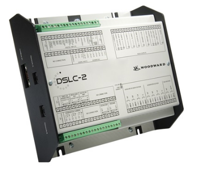
Operating Modes: Auto, Stop, and Manual, plus Load/No-Load Test modes triggered via digital inputs;
Synchronization and Paralleling: Synchronization between generator and busbar or generator and mains using slip frequency and phase matching; automatic detection of the optimal closing moment to ensure bumpless paralleling of the GCB (Generator Circuit Breaker) and MCB (Mains Circuit Breaker); supports open-transition (break-before-make) and closed-transition (make-before-break) transfers;
Soft Loading/Unloading: Gradual load pickup and shedding along a set ramp after grid connection to prevent power surges;
Load Sharing: Automatic equal distribution of active and reactive power (power factor) for up to 32 units, implemented via CAN network or LS-5 analog load-sharing lines;
Load-Dependent Start/Stop: Automatically determines the number of units to start or stop based on total load; supports fixed and dynamic priority settings to ensure units operate within their high-efficiency ranges;
Import/Export Control: Regulates power drawn from or fed to the grid at set values during grid-parallel operation, ensuring electricity is purchased only as needed and consumption limits are not exceeded;
Peak Shaving: Automatically starts units to supplement power during peak loads and stops them during off-peak periods to reduce demand charges;
PID Controllers: Three freely configurable PID loops for controlling process variables such as water temperature, water level, oil level, and pressure (e.g., in CHP heating circuits). 3. Protection Functions: A comprehensive suite of protection functions is configured in accordance with the ANSI numbering system, including: generator over/undervoltage (59/27), over/under-frequency (81O/81U), overload and reverse/under-power (32/32R/32F), three-phase unbalance (46), instantaneous overcurrent (50), earth fault (50G), definite-time overcurrent (51, compliant with IEC 255), power factor out-of-limit (55), and phase sequence error; engine over/underspeed (12/14), speed/frequency mismatch, and D+ excitation failure; mains phase displacement (78), and abnormal mains voltage/frequency. All protection functions support independent configuration of trip setpoints, time delays, and alarm levels (alarm/shutdown).4. Communication Layer
2 x CAN bus (FlexCAN): Supports CANopen (for I/O module expansion and PLC interconnection) and SAE-J1939 (direct interface with electronically controlled engine ECUs); capable of displaying and evaluating up to 100 J1939 analog parameters (SPNs);
1 x RS-232 and 1 x RS-485: Modbus RTU slave ports for SCADA monitoring and external control;
Direct Engine ECU Connection: Supports protocols such as Scania S6, MTU ADEC, Volvo EMS2/EDC4, Deutz EMR2/EMR3, MAN MFR/EDC7, SISU EEM, Cummins, and Woodward EGS02;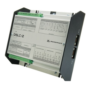
Expansion Capability: Supports expansion via CANopen of up to 32 digital inputs/32 digital outputs and 16 analog inputs/4 analog outputs (using Woodward IKD1 or Phoenix Contact IL series expansion modules); additional accessories include the RP-3000 remote panel, easYlite audible/visual alarm, and Profibus/Ethernet gateways.
5. Software Layer
FlexApp: One-click configuration of circuit breaker setup (no breaker / GCB only / GCB+MCB) to suit various system configurations;
LogicsManager: Woodward’s “soft logic” tool; uses Boolean logic and timers to combine measured values and internal states into custom control and relay functions, allowing for deep customization of operational sequences;
Event Logging: 300-entry FIFO event log with a battery-backed real-time clock; counters for cumulative running hours, start cycles, maintenance intervals, and active/reactive energy. tee-global.com Woodward
II. Operation Methods
1. Panel Operation
Features a 5.7-inch, 320×240 graphical LCD screen with soft keys; offers a clear menu structure and multi-language support (including Chinese); allows intuitive monitoring of voltage, current, frequency, power, power factor, engine speed, and unit status.
Mode switching: AUTO / STOP / MANUAL / Test (Load/No-Load) modes; switchable via the panel or digital inputs.
Manual mode allows for step-by-step execution of start, synchronization, breaker closing, loading, unloading, breaker opening, and shutdown sequences—ideal for commissioning and testing.
2. Configuration (Engineer Operation): Perform full configuration using the PC software “ToolKit” (included, connected via serial port). Key steps include:
Select application mode: Standby, AMF, Peak Shaving, Import/Export Control, CHP, Grid-Parallel, etc.;
Select circuit breaker configuration (GCB / GCB+MCB) using FlexApp;
Set system parameters: Rated voltage (120V/480V range), rated frequency, CT ratio (5A nominal), and rated power;
Configure analog input sensor types and ranges (VDO / Pt100 / 4–20mA), PID loops, and LogicsManager logic;
Set all protection thresholds and time delays, as well as synchronization closing windows (voltage, frequency, and phase angle differences);
Configure communication settings: CANopen/J1939 nodes, Modbus slave address, and ECU protocol selection.3. Remote Operation: Connects to SCADA systems via RS-485 Modbus, or to the RP-3000 remote panel and host monitoring systems via CAN network, enabling remote start/stop, setpoint adjustment (speed/frequency/voltage/active power/reactive power/power factor), and alarm monitoring.
III. Precautions (Engineer’s Notes)
Installation and Wiring
Power Supply: 12/24V DC system (supports a wide range of 8–40 VDC); maximum power consumption is 17W. Verify polarity (despite built-in protection features) and use appropriate fusing; turn off the battery charger before disconnecting the battery.
Voltage Ranges: The 100V and 400V ranges use separate terminal sets; verify the voltage level before wiring, as incorrect connection will damage the measurement circuit. While inputs are high-impedance, do not exceed rated limits (max. 150V for the 120V range; max. 600V for the 480V range).
CT Circuit: Designed for 5A CTs; must match the transformer’s secondary side. Never leave the CT secondary circuit open; short-circuit it before maintenance. Short-time withstand rating is 10 times the rated current (1 second).
Insulation Test: Terminal-to-terminal insulation withstand voltage is rated at 500 VAC (1 second); disconnect the controller or follow specific instructions when performing withstand voltage tests.
Electrostatic Protection: The controller is sensitive to static electricity; discharge static from your body before handling and avoid touching the circuit board. Commissioning and Operation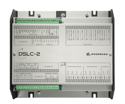
Before paralleling (with other units or the grid), verify phase sequence, synchronization display, and protection functions under no-load conditions; the synchronization closing window must be configured according to the circuit breaker’s closing time to prevent shock loading during paralleling;
Load sharing and load-dependent start/stop logic involve multiple units; test each unit individually before gradually integrating them into the system;
Critical hardware protections—such as overspeed shutdown—must be implemented independently of the controller (using separate mechanical or electrical devices); this is a mandatory requirement in the Woodward manual;
Back up parameters before making changes and verify each item after modification; ensure multi-level password protection is enabled for both the HMI and communication interfaces.
Operation and Maintenance
Environment: Operating temperature -20 to +70°C, storage temperature -30 to +80°C, humidity ≤95% (non-condensing); front panel rating is IP66/IP54 depending on the mounting method—ensure proper installation;
Regularly check event logs and counters, and perform maintenance according to the schedule; verify the order number suffix and software version when replacing spare parts.IV. Application Areas
Multi-unit Parallel Power Plants: Backup power clusters for data centers and industrial parks, featuring parallel operation of multiple units and automatic unit addition/removal based on load;
Emergency Backup (AMF/ATS): For facilities requiring high power supply continuity—such as hospitals, airports, financial institutions, and telecommunications centers—enabling automatic startup and transfer upon grid failure;
Grid-tied Operation and Peak Shaving: For captive power plants and distributed energy stations, drawing power from the grid during off-peak hours and generating power during peak hours to implement demand management and peak shaving;
Import/Export Control: Scenarios involving self-generation for self-consumption plus surplus power export to the grid, precisely controlling power import/export levels to avoid demand charge penalties;
Combined Heat and Power (CHP): Gas-fired power generation combined with waste heat recovery; utilizing PID control for process variables such as heating circuit water temperature to achieve “heat-led” or “electricity-led” operation;
Islanded/Standalone Operation: For off-grid areas such as mining sites, oil fields, and islands, providing independent power supply via multiple units operating in parallel;
Marine and Offshore: Certified by LR and ABS, suitable for ship auxiliary power plants and offshore platform power supply;
Rental Power: Supports multiple switchable parameter sets and dispatch management for mobile power stations.V. Key Benefits
Upgrading “Stand-alone Units” to a “Power Plant”: A single controller manages the automatic start/stop, synchronization, and load sharing of up to 32 generator sets, enabling truly unattended, power-plant-style operation for backup power systems;
Cost Savings: Features automatic unit addition/subtraction based on load, peak shaving, and import/export control; ensures units always operate within their high-efficiency range, reducing fuel consumption and demand charges;
Enhanced Safety: Comprehensive ANSI protection system covering the generator, engine, and mains; rapid isolation of anomalies minimizes the risk of equipment burnout and power outage incidents;
Improved Power Quality: Synchronized paralleling, soft loading/unloading, and active/reactive power sharing reduce grid-connection transients and voltage fluctuations;
Open Integration: Supports CAN/J1939, Modbus, extended I/O, and remote panels; easily integrates with SCADA and energy management systems, making power generation assets fully visible and manageable;
Flexibility and Versatility: Features FlexApp, LogicsManager, and PID free configuration; a single hardware platform supports various business models—including backup power, grid-parallel operation, peak shaving, CHP, and import/export control—allowing OEMs to meet almost all customer requirements with one platform.
VI. Summary
The easYgen-3200-P2 (8440-2052) is Woodward’s “multi-unit paralleling + multifunctional application” class generator controller. Capable of both reliable stand-alone operation and managing up to 32 units for automatic paralleling, load sharing, grid-parallel peak shaving, and import/export control, it serves as the core “master controller” for backup power systems, distributed energy resources, and marine power plants. If you would like to proceed, I can elaborate on the terminal definitions, typical wiring diagrams, or the ToolKit configuration process.
Model recommendation:
8440-2047
SPM-D11 8440-1703
SPM-D11 8440-1706
8440-2085
8440-1800
8440-1925
8440-1934
8440-1546
8440-1894
8440-2096
8440-1947
8440-2150
More……
admin –
Series: easYgen-3000 Generator Set Integrated Controller Platform
Part Number: 8440-2052 = easYgen-3200-P2, Panel Mount Type with Front-facing Color Graphic Display
Turbo Governor: Specifically designed for gas turbine/steam turbine generator sets, integrating speed regulation, synchronous parallel operation, and load distribution control. It’s not just a simple speed governor; it’s a dedicated main control unit for turbine generators.
II. Core Hardware Specifications
Electrical and Dimensional Specifications
Power Supply: 12/24 VDC wide-range battery power supply, maximum power consumption 17~19W
Panel Mount Dimensions: 282 (W) × 216 (H) × 96 (D) mm; Rear Mount Base: 250 × 227 × 50 mm
Operating Temperature: -20℃ ~ +70℃, suitable for wide-temperature operating conditions in offshore, oil fields, and power plants.
Certifications: UL, CE, marine classification certifications; applicable to offshore oil and gas, and marine turbine generators.
I/O and Communication
Switch Inputs: Up to 32 isolated DI/DO channels, supporting unit start/stop and circuit breaker GCB/MCB control.
Analog Inputs: FlexIn universal analog inputs, compatible with 0/4-20mA, resistance temperature/pressure sensors, and VDO transmitters.
Communication Interfaces (essential for turbine units):
CAN J1939 FlexCAN: interface with turbine ECU, Woodward EG3 electronic speed controller, and hydraulic actuators.
Dual Ethernet IP, Modbus TCP/RTU, RS232, and USB debugging ports.
Analog Speed/Voltage Regulating Output: directly drives turbine speed actuators, generator AVR voltage regulator boards, etc. Measurement Capabilities
Supports single-phase/three-phase three-wire/four-wire generator voltage and current acquisition, frequency… 40~85Hz (covering the 50/60Hz power grid).
III. Core Functions Exclusive to Turbo Turbine Units
1. Turbine Speed Closed-Loop Regulation (Governor Core)
Adaptive nonlinear PID + feedforward compensation algorithm, suitable for the dynamic fluctuations of gas turbines and steam turbines.
Precise output adjustment via slip/differential frequency, automatically matching grid frequency, solving the problem of turbine speed oscillation during load changes.
Can be linked with all Woodward series hydraulic/electronic actuators, replacing independent speed governors for integrated control.
2. Multi-Unit Synchronization and Load Distribution (Turbine Power Plant Core)
Single unit grid connection, islanded parallel operation of multiple turbine units, grid-connected operation compatibility, automatic rotational control of up to 32 units.
Open/closed-loop switching, soft loading/unloading, reactive power equalization, preventing turbine reverse power and circulating current damage to the turbine.
Built-in synchronization capture logic, automatically adjusting turbine speed and generator voltage to achieve shock-free grid connection.
3. Complete Unit Protection (Turbine Dedicated)
30 Multiple programmable protection features covering turbine-specific faults:
Electrical: Over/under frequency, over/under voltage, reverse power, overload, short circuit, differential protection
Turbine body: Low lubricating oil pressure, high exhaust temperature, cylinder temperature difference, overspeed shutdown, vibration interlock, fuel failure
Black start, power failure AMF, automatic mains transfer switch, peak shaving, CHP logic
4. Programmable Logic (LogicsManager)
Built-in Boolean logic editor, no external PLC required, allows customization of turbine start/stop sequence, purging, warm-up, and shutdown cooling processes, adaptable to control logic of gas/steam turbine units from different manufacturers.
IV. Typical Application Scenarios (Turbo Turbine Operating Conditions)
Offshore/Land-based Gas Turbine Generator Sets in Oil and Gas Fields (Island Microgrids)
Self-owned Power Plant Steam Turbines, Combined Cycle Cogeneration (CHP) Units
Marine Turbine Main/Emergency Generator Sets (Maritime Certification)
Large Backup Turbine Power Stations in Data Centers, Steel Mills, and Cement Plants
Multi-Turbine Cooperative Control in Distributed Energy Microgrids
https://www.weikunfadacai1.com/product/abb-gfd563a102-3bhe046836r0102/
https://www.weikunfadacai1.com/product/abb-gfd563a101/
https://www.weikunfadacai1.com/product/s-093h-abb-high-voltage-inverter-phase-module-3bhb030478r0309-s-093h/
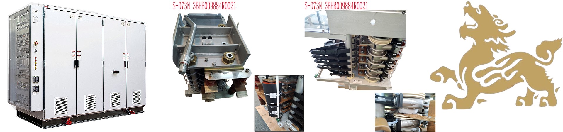
https://www.weikunfadacai1.com/product/s-073n-abb-high-voltage-inverter-phase-module-3bhb009884r0021-s-073n/
https://www.weikunfadacai1.com/product/ppd513aoc-100440-3bhe039724r0c3d-ac800pec-system-excitation-controller-ppd513aoc-100440/
https://www.weikunfadacai1.com/product/ppd113b03-3bhe023584r2365/
https://www.weikunfadacai1.com/product/3bhe023584r2365-cpu-abb/
https://www.weikunfadacai1.com/product/abb-ppd113b03-26-100110-3bhe023584r2634/
https://www.weikunfadacai1.com/product/abb-ppd113b03-26-100110-3bhe023584r2634/
https://www.weikunfadacai1.com/product/abb-3bhe023584r2365-2/
https://www.weikunfadacai1.com/product/3bhe023584r2365-controller-abb/
https://www.weikunfadacai1.com/product/max-4-11-03-128-08-1-1-00-elau-servo-drive/
https://www.weikunfadacai1.com/product/easygen-3000-8440-2052-turbo-governor-8440-2052/
https://www.weikunfadacai1.com/product/abb-central-processing-unit-ucd208a101-3bhe020018r0101/
https://www.weikunfadacai1.com/product/woodward-8440-1947/
https://www.weikunfadacai1.com/product/woodward-8440-1947/
https://www.weikunfadacai1.com/product/abb-ppd512a10-150000/
https://www.weikunfadacai1.com/product/woodward-8440-1868/
https://www.weikunfadacai1.com/product/woodward-easygen-3500xt-8440-2085/
admin –
RMS voltage/current detection (harmonic interference resistant), CAN network communication (supports SAE-J1939 and proprietary OEM protocols), and serial Modbus RTU communication, allowing seamless integration with SCADA or PLC systems.
Parallel Connection and Load Sharing
Supports parallel load sharing for up to 32 generator sets, suitable for complex power distribution systems (such as multi-feeder sectionalization, circuit breaker control), meeting the emergency backup power needs of data centers, hospitals, and other distributed generation scenarios such as microgrids and combined heat and power (CHP).
Communication and Programmability
Built-in LogicsManager programmable logic functions, typically eliminating the need for additional PLC control, but allowing flexible integration with SCADA or PLC-based control systems. Supports communication with the RP-3000 remote panel via the CANopen protocol (up to 250 meters).
admin –
Safety and Alarms
Supports multi-level customizable alarm thresholds. Verify the effectiveness of alarm logic and protection functions. Faulty module replacement must be performed under redundant configuration; verify status using original manufacturer diagnostic tools.
Maintenance Methods
Daily Inspections
Quarterly check controller status, connector cleanliness, and heat dissipation; perform system-level testing (e.g., redundancy switching, protection logic verification) every six months. Troubleshooting
Replacing a faulty module must be done under redundant configuration. Update the firmware to the latest version to activate new functions (such as 5G communication support). Predict fault points based on operational data (e.g., capacitor aging, relay contact wear).