
Description
All products on this website are specialized items subject to fluctuating market prices.
Actual pricing is based on quotes provided by customer service; listed prices are not final.
Please confirm details—such as model number, product specifications, and price—with customer service before placing an order.
Please contact customer service for further information.
I. Product Overview
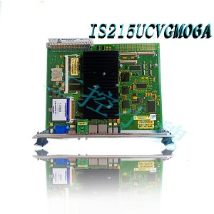
The IS220UCSAH1A is a general-purpose embedded controller module within the GE Vernova (formerly GE Power) Mark VIe turbine control system architecture; it is a base model in the UC series of distributed control units. Designed for small-to-medium gas turbines, steam turbines, plant auxiliary systems, and industrial process control applications, this module provides deterministic real-time control, data acquisition, and interlocking protection capabilities. It serves as a core hardware unit for field-level distributed control within the Mark VIe system. Developed using a PowerPC architecture processor and the QNX real-time operating system, the module supports either standalone operation or a dual-unit hot-standby redundant configuration, allowing for flexible adaptation to industrial control requirements of varying scales.
II. Operating Principles
2.1 Hardware Architecture and Computing Foundation
The IS220UCSAH1A utilizes a Freescale PowerQUICC II Pro 667 MHz processor as its core computing unit. It is equipped with 256 MB of DDR SDRAM and 1 GB of CompactFlash storage. Featuring a fully sealed, fanless thermal design and low-power hardware architecture, it ensures stable, continuous 24/7 operation. The module includes an integrated power management unit that supports a wide DC input range of 18–36V, making it fully compatible with standard industrial 24V DC power systems. Additionally, it incorporates protection circuits against overvoltage, overcurrent, and reverse polarity, effectively preventing power anomalies from damaging the core processor and storage components. 2.2 Real-Time Operating System and Control Execution Mechanism
This module runs the QNX Neutrino real-time multitasking operating system. Leveraging a microkernel architecture and priority-based preemptive scheduling, it maintains a stable scan cycle of 50–100 ms for standard control tasks and ensures a response time of ≤50 ms for critical safety protection tasks, fully meeting the real-time requirements of critical industrial rotating equipment. Its control execution follows a deterministic “Acquisition – Computation – Output” cyclic process:
Data Acquisition Phase: Real-time reading of analog and digital signals from downstream I/O modules via the dedicated IONet bus, with automatic signal filtering, range scaling, and validity checking;
Logic Computation Phase: Parallel execution of user-configured control algorithms—such as PID regulation, feed-forward control, ratio control, and interlock protection—calculating optimal output commands based on setpoints and field feedback values;
Output Generation Phase: Transmission of computation results via the IONet bus to corresponding I/O channels to drive field actuators (e.g., valves, motors), while simultaneously uploading operating status and process data to the supervisory monitoring system.
2.3 Communication and Redundancy Principles
The IS220UCSAH1A is equipped with two 10/100 Mbps IONet Ethernet interfaces, one RS-485 industrial bus interface, and one USB debugging interface, natively supporting dual-network redundant communication. In a hot-standby redundancy configuration, the primary and backup controllers exchange operational data, program status, and I/O image data in real-time via a dedicated synchronization link. Should the primary controller experience a hardware failure or communication interruption, the backup controller performs a bumpless switchover within ≤10 ms, ensuring continuous control of field equipment and preventing production downtime. Additionally, the module supports dual-power redundant inputs, allowing the system to maintain stable operation even if a single power supply circuit fails.2.4 Distributed Expansion Principles
The controller supports the connection of up to 16 I/O modules via the backplane bus or IONet network, accommodating a maximum of 1,024 I/O points. It offers flexible configuration with various I/O terminal boards—including analog I/O, digital I/O, thermocouple/RTD inputs, and pulse inputs—to meet diverse on-site signal acquisition and control requirements, thereby establishing a distributed industrial control architecture characterized by “centralized monitoring and distributed control.”
III. Core Technical Advantages
3.1 High-Determinism Real-Time Control Capability
Powered by the QNX real-time operating system and a dedicated hardware acceleration architecture, the IS220UCSAH1A delivers stable, millisecond-level control cycles. Its core protection logic operates without scheduling jitter, offering control precision and response speeds far superior to general-purpose PLCs. This enables it to meet the rigorous real-time control demands of high-speed rotating equipment, such as gas and steam turbines.
3.2 End-to-End Redundancy Design for Significantly Reduced Downtime Risk
Controller Level: Supports dual-module hot-standby redundancy with a primary/backup switchover time of ≤10 ms; the transition occurs without control disturbances or data loss.
Power Supply Level: Features dual-channel redundant power inputs compatible with a wide voltage range (18–36 V DC); a failure in a single power channel does not disrupt system operation.
Communication Level: Utilizes dual Ethernet link redundancy to prevent loss of control caused by a single cable or interface failure. This end-to-end redundancy design can reduce unplanned downtime in industrial settings by over 25%, significantly enhancing the operational continuity of critical equipment. 3.3 High Environmental Adaptability for Harsh Industrial Conditions
The module features a fanless, fully sealed design with a conformal coating and EMI shielding capabilities. It operates within a temperature range of -40°C to +70°C and withstands storage temperatures from -55°C to +85°C. With a vibration resistance rating of 5g (10–2000 Hz), it ensures stable, long-term operation in environments characterized by high temperatures, high humidity, dust, and strong electromagnetic interference—such as those found in metallurgy, power generation, and petrochemical facilities—without requiring frequent maintenance.
3.4 Flexible Integration and Expansion Capabilities
It natively supports mainstream industrial communication protocols such as Modbus TCP/IP, Modbus RTU, and SRTP, enabling seamless connectivity with plant-wide DCS systems, supervisory software, and third-party industrial equipment. Additionally, it supports the flexible addition of up to 16 I/O modules, allowing the I/O point count to be configured according to specific site requirements, thereby effectively reducing engineering costs associated with system expansion and upgrades.
3.5 Convenient O&M and Remote Diagnostics
The module’s front panel is equipped with LED status indicators that provide a clear view of power, operation, communication, and fault status. Built-in comprehensive self-diagnostic functions monitor internal hardware health, communication link quality, and I/O channel validity in real-time. When used with GE Proficy industrial software, it enables remote troubleshooting and parameter debugging, reducing on-site fault localization time by 30% and significantly lowering the workload and travel costs for O&M personnel.
4. Core Role in Key Application Industries
4.1 Power Generation Industry: Precision Control and Safety Barrier for Power Equipment
Thermal Power Generation: Serving as the control core for the auxiliary systems of steam turbine-generator units, it collects real-time data—such as turbine bearing pad temperatures, lubricating oil pressure, steam parameters, and rotational speed. It regulates auxiliary equipment (e.g., lubricating oil pumps, condensate pumps, and governing oil pumps) via closed-loop PID algorithms while executing interlocking protection logic for conditions like overspeed, over-temperature, and low oil pressure, thereby ensuring the safe and stable operation of the main unit.
Gas-Steam Combined Cycle Power Generation: Used for the local control of gas turbine auxiliary systems and heat recovery steam generators (HRSGs), it enables precise regulation of fuel bypass valves, cooling fans, and feedwater pumps. It works in tandem with the main controller to optimize combustion efficiency and reduce both auxiliary power consumption and nitrogen oxide (NOx) emissions.
Small-to-Medium Hydropower and New Energy: Compatible with hydropower governing systems and wind turbine pitch control auxiliaries, it facilitates precise speed regulation for hydro-generator units and provides status monitoring and protection for wind turbines, thereby enhancing grid-connection stability for renewable energy generation.
4.2 Petrochemical Industry: Stable Support for Compressor Units and Process Operations
In control systems for large centrifugal and reciprocating compressors used in refining, ethylene, and fertilizer production facilities, the IS220UCSAH1A monitors parameters such as inlet/outlet pressure, temperature, vibration, and motor current in real time. It employs adaptive control algorithms to dynamically adjust anti-surge valve openings and unit rotational speeds, effectively mitigating surge risks. Simultaneously, it performs closed-loop regulation of process parameters—such as those for distillation and reaction—ensuring the continuity and stability of production processes (e.g., feedstock transport and product separation) and minimizing product quality risks and safety hazards caused by process fluctuations. 4.3 Metallurgical Industry: Ensuring Reliable Operation of Power Equipment
In the control systems for large-scale power equipment—such as blast furnace blowers, oxygen generation units, and dust extraction fans—this controller precisely adjusts fan speeds and damper openings based on blast furnace smelting process requirements. It monitors critical parameters in real-time, including bearing temperatures, motor winding temperatures, and equipment vibration. Under abnormal operating conditions, it rapidly triggers load reduction or shutdown protection, thereby preventing blast furnace outages caused by equipment damage and significantly reducing the massive economic losses associated with unplanned downtime.
4.4 General Industrial Automation
Widely applied in scenarios such as discrete manufacturing lines, intelligent manufacturing cells, municipal water treatment systems, and building automation, this controller provides reliable logic control and analog regulation capabilities. It simplifies system architecture, reduces the workload for engineering implementation, lowers overall operation and maintenance costs, and enhances the long-term operational stability of industrial automation systems.
5. Standard Operation and Commissioning Procedures
5.1 Installation and Wiring
Module Installation: Steadily insert the IS220UCSAH1A into the corresponding DIN rail or backplane slot of the Mark VIe control cabinet; tighten the mounting screws on both sides to ensure a secure connection between the module and the backplane connector, ensuring there is no looseness;
Power Wiring: Connect the 24V DC power supply to the power terminals; a dual-redundant power supply scheme is preferred; verify positive and negative polarity before wiring to prevent reverse polarity connection;
Grounding: Securely connect the module chassis grounding terminal to the control cabinet’s grounding busbar; ensure grounding resistance is ≤4Ω to guarantee electromagnetic compatibility and electrostatic protection;
Communication Wiring: Use shielded Ethernet cables to connect the IONet interface to downstream I/O modules and industrial switches; use shielded twisted-pair cables for the RS-485 interface, ensuring the cable shield is securely grounded at one end.
5.2 Power-up and System Initialization
Before powering up, use a multimeter to measure the supply voltage and confirm it is within the 18–36V DC range; inspect all wiring to ensure there are no short circuits or loose connections;
Close the power switch and observe the module’s front panel indicators: the power indicator (PWR) should remain steadily lit, and the run indicator (RUN) should transition from flashing to steadily lit, indicating that the operating system and control program initialization is complete;
The initialization process takes approximately 30–60 seconds; do not forcibly disconnect power during this time to avoid damaging operating system files or user programs.5.3 Program Configuration and Download
Connect the debugging computer via the USB interface and use ToolboxST—the dedicated programming software for the GE Mark VIe—to create a new control project; complete I/O point mapping, control logic configuration, and protection parameter setup;
Compile the control program to ensure there are no syntax errors, then download it to the controller via USB or Ethernet; the controller will automatically restart and load the new program upon completion of the download;
Enter online monitoring mode to verify that the acquired point values and logic operation results align with the design specifications.
5.4 On-line Commissioning and Functional Verification
Gradually connect field I/O signals to verify the accuracy of analog signal acquisition, as well as the accuracy and real-time performance of digital status feedback;
Conduct closed-loop control circuit testing: manually modify setpoints, observe the response curves of actuators, and tune PID parameters to achieve optimal control performance;
Test interlocking protection logic by simulating fault signals to verify the correctness of protection actions and response times;
In redundant configurations, simulate faults such as primary controller power loss or communication interruption to verify the bumpless transfer capability and data consistency of the backup controller.
5.5 Routine Operation
Under normal operating conditions, no manual intervention with the controller unit itself is required; operators can view operating parameters, modify setpoints, and query historical data via the supervisory monitoring system; periodically read controller diagnostic logs using the programming software to identify and troubleshoot potential issues.
6. Precautions for Operation and Maintenance
6.1 Power Supply and Grounding Precautions
Ensure a stable power supply with a peak voltage ripple of ≤5%; do not share the power circuit with high-power variable-frequency drives or starting equipment to prevent controller restarts caused by power interference;
Reliable protective grounding is mandatory; do not connect the grounding terminal to the AC neutral line or the equipment chassis to avoid common-mode interference damaging communication interfaces and core chips;
Before powering up after a prolonged shutdown, inspect power terminals for oxidation or looseness, and verify normal power supply conditions before gradually closing the circuit breakers.
6.2 Network Communication Precautions
The IONet control network requires shielded Ethernet cables meeting GE specifications; the total bus length and number of nodes must comply with protocol standards to prevent excessive communication latency or reduced determinism caused by an oversized network topology;
Do not connect the controller’s Ethernet interface to office networks or the public internet to prevent virus attacks or network storms from compromising real-time control performance and system security;
In environments with high levels of industrial dust, clean communication connector contacts quarterly and inspect connectors for looseness or oxidation to ensure communication link quality.
6.3 Environmental and Hardware Maintenance Precautions
Maintain a clean operating environment for the modules; prevent heavy dust or corrosive gases from accumulating on module surfaces, and ensure that heat dissipation and ventilation areas remain unobstructed to allow for effective natural cooling;
Hot-swapping controller modules is strictly prohibited; disconnect the corresponding power supply before inserting, removing, or replacing components to prevent hardware interface or backplane damage caused by hot-swapping;
Conduct a comprehensive inspection every six months to check module indicator status, supply voltage, and communication quality; clean accumulated dust from inside the control cabinet; and identify potential issues related to heat dissipation and wiring.6.4 Precautions for Program and Firmware Management
Before modifying control programs, a complete backup of the original program and parameter configuration must be created. Ensure the program compiles without errors before downloading to prevent field equipment malfunctions caused by faulty logic;
Controller firmware upgrades must utilize official, stable versions released by GE. Power must not be interrupted during the upgrade process, and all control and protection functions must be fully verified after the upgrade is complete;
Unauthorized modification of internal system parameters or real-time scheduling priorities is prohibited to avoid compromising control determinism and redundancy switching capabilities.
6.5 Precautions for Troubleshooting
Prioritize locating faults using panel indicator lights and software diagnostic information. Follow the troubleshooting sequence of “power supply first, then hardware; communication first, then program” to minimize downtime;
If the controller experiences system freezes or frequent restarts, prioritize checking power quality and grounding issues. Rule out external interference before investigating program logic or hardware faults;
In the event of hardware failure, replace the unit with an original spare part of the same model. After replacement, reload the program and configuration parameters, and fully verify functionality before resuming formal operation.
VII. Conclusion
The GE IS220UCSAH1A embedded controller module serves as a core hardware platform for controlling critical equipment in industries such as power generation, petrochemicals, and metallurgy, thanks to its highly deterministic real-time control capabilities, end-to-end redundancy design, and adaptability to harsh operating conditions. As a fundamental control unit of the Mark VIe control system, it can independently handle the complete control and protection of small-to-medium-sized equipment or function as a distributed node within a large-scale plant-wide control system, playing an irreplaceable role in ensuring production safety, enhancing operational efficiency, and reducing lifecycle operation and maintenance costs.
Model recommendation:
IS220UCSAH1A
IS220YDIAS1B
IS220YDIAS1AJA4F19X
IS220YDIAS1B
IS220YDIAS1A
IS220PTURH1A
IS220PTCCH1A
IS220PAICH1A
IS220PAICH2A
IS220PAOCH1A
1770-950
HA339587A-ETU-003
M44I-16-0-ITEM-99588
IS420UCSBH1A
IS420UCSBH1A-UCSB
IS420UCSCH1A-UCSC
IS420YDIAS1B
IS420PUAAH1A
IS420UCSCH2A-C-V0.1-A
IS420UCSCH1B
IS220YDIAS1A
IS200AEPAH1BKE
IS200TDBSH2ACC
IS220PRTDH1A
IS220PRTDH1A
IS220PSCAH1A
IS220PVIBH1A
IS200JPDEG1A
IS200VPROH1BEF
IS200VPROH2B
More……

admin –
The IS220UCSAH1A is a Processor/Controller created by General Electric for the Mark VI system. Designed to manage gas or steam turbines, the Mark VI platform was released by GE as part of the Speedtronic line.
admin –
For the auxiliary control system of the combined-cycle waste heat boiler, the IS220UCSAH1A UCSA embedded controller is utilized. Serving as a distributed control node for auxiliary equipment, it handles interlocking logic for water pumps, fans, and valves with stable performance. It supports a dual-controller hot-standby redundancy configuration, ensuring bumpless switching between the primary and backup units. On-board LED indicators facilitate rapid on-site diagnosis of communication or hardware faults. Important note: The UCSA is an embedded auxiliary controller; its hardware functionality differs from that of the UCSB/UCSC main controllers, meaning they are not directly interchangeable. When replacing a unit, the complete ToolboxST project must be downloaded to the new controller. Additionally, sufficient space must be reserved during installation to allow for heat dissipation.
https://www.weikunfadacai1.com/product/is220ucsah1a-ge/