
Description
Many products are not yet listed. Please contact us for more product information.
If the product model differs from the displayed image, the model number shall prevail. Please contact us for specific product images; we will arrange to take photos in our warehouse for confirmation.
We have 76 shared warehouses worldwide, so it may sometimes take several hours to return an accurate result. We apologize for any inconvenience. Of course, we will respond to your inquiries as soon as possible.
Other names for 8237-1600:
Editable Controller 8237-1600
Analog Unit 8237-1600
The Woodward 8237-1600 is a high-performance digital speed controller, belonging to Woodward’s industrial control product line. This digital speed control/regulation unit for engine/turbine systems, integrated into Woodward’s digital speed control and turbine control system, enables precise speed control and condition monitoring. Designed for industrial environments, it is widely used in power generation, oil and gas, marine, and industrial automation. Primarily used for speed and power control of turbines and generator sets, it ensures stable and efficient equipment operation. Its core functions include current-to-pressure signal conversion, servo position control, and speed regulation, supporting integration with PLC and DCS systems.
Product Positioning and Technical Background
Brand Background: Founded in 1870, Woodward is a leading global supplier of industrial control and energy systems, specializing in control and speed regulation systems for engines, turbine machinery (such as steam turbines and gas turbines), and generator sets. Its products are widely used in power generation, marine, petrochemical, and aerospace industries.
Speed Controller Type: Woodward’s digital speed controllers are microprocessor-based, with typical models including 505/505E, PEAK150, 2301A/D-ST, and 5009. They support speed/load control, overspeed protection, load sharing, and synchronization control, and are compatible with analog signals (4-20mA), digital communication (DeviceNet), and speed sensor input.
Technical Features
Speed Control: Achieves precise speed regulation through a PID algorithm, supporting stable operation under no-load and full-load conditions.
Overspeed Protection: A triple-redundant overspeed protection module (e.g., ProTech 203) independent of the control system prevents equipment damage due to overspeed.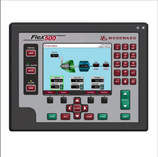
Redundant Design: Key components (such as CPU and I/O modules) adopt a triple-redundant (TMR) architecture to improve system reliability.
Interface Compatibility: Supports speed sensors (magnetoresistive/inductive), actuators (electro-hydraulic converter CPC, servo valve driver SPC), and analog/digital input/output.
Environmental Adaptability: Operating temperature range -25℃ to 65℃ (panel-mounted) or -20℃ to 60℃ (rack-mounted), protection level meets industrial environment requirements.
High Precision and Reliability: Utilizes advanced sensing and algorithms to ensure long-term operational accuracy and adaptability to harsh industrial environments.
Durable Design: IP67 protection, wide operating temperature range, and vibration-resistant design, suitable for high-intensity operating scenarios.
Ease of Use: Modular design supports rapid installation and maintenance, compatible with multiple control protocols, reducing system integration difficulty.
Redundancy and Safety: Some models support triple redundancy configuration (e.g., 5009 controller) to meet high reliability requirements, equipped with overspeed protection.
Electrical Parameters: Input voltage 24V DC, output signal coverage 0-10V DC, 4-20mA, 0-10 kHz, maximum output power 100W, current capacity 2A.
Accuracy and Response: Accuracy up to ±0.25%FS (full scale), ±0.1%FS in some scenarios; response time <10ms; temperature range -40°C to 85°C (some models -10°C to 60°C).
Physical Characteristics: Dimensions approximately 120mm × 80mm × 30mm; weight 0.25kg; aluminum alloy housing; IP67 protection rating; supports DIN rail mounting.
Communication and Compatibility: Equipped with an RS485 interface, supports ProfiBus protocol, compatible with Woodward 505/505E, 2301A and other controllers, as well as Siemens, Rockwell, and other brand systems.
Role in the System:
As part of the digital speed control loop: Speed sensor →8237-1600 (and related control electronics) → Actuator → Engine/Turbine.
Suitable for:
Constant-speed generator sets
Variable-speed mechanical drive systems
Steam turbine speed control systems requiring precise speed and load control.
Application Areas and Typical Scenarios
Industrial turbines: Used for speed/load control of steam turbines and gas turbines, such as drive systems in power plants and chemical plants.
Marine and aviation: Speed control and power management of marine engines and aircraft turbine engines.
Generator sets: Speed and load distribution control of generator sets driven by diesel engines and gas engines, supporting islanded or grid-connected operation.
Oil and gas: Controlling turbines in drilling platforms and pumping stations to achieve precise pressure and flow regulation and reduce energy consumption.
Marine engineering: Used for speed control of ship main engines and auxiliary engines to ensure navigation stability and power system reliability.
Retrofitting existing engines: Replacing traditional mechanical hydraulic governors (such as PG-PL, UG8) to improve control accuracy and automation levels.
Installation and Maintenance Points
Installation Requirements: Strictly follow wiring diagrams and mechanical installation specifications, ensuring sensor clearance (e.g., 0.38-0.51mm), actuator stroke matching, and configuring an independent overspeed protection device.
Commissioning Procedure: Configure parameters using dedicated software (e.g., ACT), including PID gain, speed setting, protection thresholds, etc., and dynamically adjust according to load characteristics..jpg)
Fault Diagnosis: Common problems include abnormal sensor signals, actuator jamming, power fluctuations, etc. Fault codes should be read using LED indicators or commissioning tools, and grounding, shielding, and connection reliability should be checked.
Common Fault Causes in Turbine Applications
Power, Wiring, and Electromagnetic Compatibility
Woodward electronic speed controllers and panels use electrostatically sensitive components; improper operation, poor grounding, or surges can damage circuit boards or cause intermittent failures.
General transmitter and control electronics guidelines indicate that wiring faults, EMI/RFI, reverse polarity, and poor shielding can lead to unstable readings or complete failure.
Typical Symptoms
The controller fails to start or resets randomly; the 4-20 mA input/output is unstable; or it trips falsely when operating near a high-power motor or circuit breaker.
Pneumatic/I-P Side: Air Quality, Contamination, Leakage
As an I/P converter, 8237-1600 relies on clean, dry, controlled instrument air; contaminants (oil, water, particles) and moisture in the compressed air are well-known causes of pressure unit failure and output instability.
The General I/P Troubleshooting Guide lists blocked orifices, dirty baffle nozzles, out-of-range supply pressure, and leaks as major causes of low output pressure, drift, or excessive noise.
Typical Symptoms
The output pressure is stuck at zero or minimum/maximum, the response is slow, the turbine speed fluctuates, or the rated speed cannot be reached even when the command signal is correct.
Hydraulic/Oil Circuit Problems in the Governor Chain
The Woodward Hydraulic Governor Manual states that incorrect oil grade, deteriorated/foaming oil, high temperature, or low oil level can all reduce stability and ultimately lead to governor malfunction or failure.
Industry guidelines indicate that lubrication problems in turbine governor valves, air in the control oil, and excessively low control oil pressure are common causes of valve malfunction.
Typical Symptoms
Uneven speed under load, slow or stuck actuator operation, inability to restart after a hot start, or overspeed/underspeed tripping during load changes.
Sensor and Feedback Problems
Turbine speed control systems rely on proximity probes/magnetic pickups and auxiliary feedback; Woodward and other technical specifications emphasize that poor speed signals, incorrect probe gaps, or damaged wiring can cause control instability or protection trips, which may be misdiagnosed as “governor malfunction.”
Pressure/feedback transmitters in the circuit can fail due to overpressure, corrosion, moisture ingress, or blockage, all of which can lead to feedback errors and obvious controller malfunctions.
Typical Symptoms
Sudden fluctuations in displayed speed or load, governor switching to backup sensor, recurring overspeed or signal loss tripping, but without obvious mechanical cause.
Configuration and Tuning Errors
Woodward’s digital governors (e.g., 505/723 series) indicate that even with proper hardware, incorrect setpoints, unsaved calibration setpoints, or misconfigured droop/critical speed avoidance functions can lead to poor speed control, oscillation, or unexpected tripping.
If a new module is installed using default parameters, or a module is copied from an incompatible unit, the resulting control behavior will be unstable due to the turbine’s unique dynamic characteristics, especially near critical speeds.
Typical Symptoms
Performs well under certain loads but oscillates or trips at certain speeds, frequently operates within the critical speed range, or exhibits behavior that changes immediately after parameter editing or controller replacement.
Environmental Factors, Aging, and Lack of Comprehensive Maintenance
Woodward points out that turbines, valves, actuators, and governors have a service life exceeding 30 years, but require regular overhauls or maintenance to maintain reliability, especially under harsh temperature and vibration conditions.
General pressure/field transmitters exposed to extreme temperature cycles, vibration, and humid environments are prone to problems such as weld cracking, corrosion, or seal failure over time.
Typical Symptoms
Increasing number of false trips, more frequent calibration drift, cracks in the housing or connectors, and intermittent failures related to ambient temperature or vibration.
Proven Troubleshooting Procedures for Truly Restoring Reliability
The following are practical operating procedures commonly used in many power plants for Woodward turbine speed control systems. Adjust details according to your specific turbine and always follow the original equipment manufacturer’s (OEM) operating procedures.
Step 1 – Check Power Supply, Grounding, and Basic Health
Check that the DC power supply to the 8701-758 is within the specified range (typically nominally 24 Vdc, or as indicated on your nameplate) and stable under load.
Check grounding and shielding: Ensure the control panel and 8701-758 grounding references match the turbine instrument grounding; clean and tighten terminals; keep signal cables away from high-voltage lines to reduce EMI, following standard EMC specifications.
Verify that the controller starts correctly. If available, use the relevant Woodward panel status menu/diagnostic display (many interfaces offer dedicated system/I-O status and alarm menus for troubleshooting).
Step 2 – Check Instrument Air/I-P Chain
Measure the supply air pressure at the 8701-758 inlet and verify that it is within the specified range and stable (typically around 20–30 psi for 3–15 psi output stages; check your specifications).
Check the air system for water, oil, or particulate matter; compressed air guidelines indicate that moisture and contaminants can cause drift, corrosion, and orifice blockage, thus reducing the performance of the pressure unit. If the output pressure is low or unstable, follow the I/P maintenance procedure: isolate the air, remove and clean the micro-orifices and baffle/nozzle surfaces, remove debris with a suitable wire/needle, and then reassemble as recommended in the I/P troubleshooting guide.
Perform a leak test on all pipes, joints, and actuator diaphragms; failure to establish and maintain the specified 3-15 psi range indicates a leak or actuator problem, not an electronic malfunction.
Step 3 – Check Hydraulic Oil and Actuator Performance (if applicable)
Check the level, temperature, and cleanliness of the governor and turbine control oil; the Woodward manual clearly states that incorrect or degraded oil, as well as overheating, are causes of governor instability or malfunction. Following the recommendations in the governor valve troubleshooting guide, purge any trapped air from the governor oil circuitry and verify that the control oil pressure meets specifications.
Perform a stroke test on the actuator using analog I/P or electrical signals (according to OEM procedures) to check if the valve moves smoothly throughout its stroke without sticking, hysteresis, or delay.
Step 4 – Verify Sensor and Signal Integrity
Check the speed pickup/proximity probe: ensure correct installation, proper air gap, good cable condition, and adequate shielding; poor speed signal quality is a major cause of unstable turbine speed control.
Check the calibration of the feedback transmitters (pressure, position, load), overrange history, signs of corrosion or moisture ingress, and port blockages; all are known causes of pressure instrument drift or malfunction.
Inject a 4-20 mA signal into the inputs of the 8237-1600 using a known good loop calibrator and verify that the output pressure correctly tracks the command to determine if the problem is with the module itself.
Step 5 – Check Configuration, Tuning, and Logic
Retrieve and back up the existing governor configuration; Woodward’s 723/505 documentation warns that unsaved or incorrect setpoints may revert to their original state or cause malfunctions if a power failure and restart occur.
Compare key parameters (speed setpoint, gain, droop, critical speed avoidance band, start-up ramp rate, trip limit) with the OEM-approved turbine settings.
If oscillations or wobbling occur, adjust the gain/compensation according to the step-by-step adjustment section in the governor manual (e.g., compensation pin or digital PID item), always under controlled conditions and with safe trip capability.
Step 6 – Decide on Repair or Replacement
If, after following the steps above, 8237-1600 fails a basic benchtop test (e.g., correct air supply, but no or unstable pressure output for a clean 4-20 mA input), the module is internally damaged and should be sent to a Woodward-authorized repair/overhaul service for repair/overhaul, rather than being opened in the field.
Woodward particularly encourages factory overhauls of gas/steam turbine governors, actuators, and valves to maintain the reliability of long-life assets. This typically includes component replacement, calibration, and functional testing.
Long-Term Reliability Improvement
To prevent recurring failures and extend the Mean Time Between Failures (MTBF) of systems based on 8237-1600:
Implement a compressed air quality program (dryer, filters, periodic dew point checks) and record maintenance of I/P orifice and baffle/nozzle cleaning, as contamination is one of the leading causes of pneumatic control failures.
Following the recommendations in the Woodward Hydraulic Governor Manual, enforce governor oil quality and temperature limits through regular sampling, oil change cycles, and inspection of control oil filters.
According to pressure gauge best practices, implement regular calibration and functional testing procedures for speed sensors and transmitters, including checking for moisture ingress and corrosion.
Strictly adhere to electrostatic discharge protection measures, proper grounding, and cable management as outlined in the control panel to protect sensitive digital electronics and reduce tripping caused by interference. Maintain a controlled copy of the approved governor configuration and a change management process to track, review, and roll back any parameter edits that lead to instability.
All products on this website are specialty items, and market prices are constantly fluctuating.
Please refer to customer service for a quote, as the price is not accurate as it may be for new products.
Please confirm the model, product, price, and other details with customer service before placing an order. This website is currently in use.
New items are available for sale; please contact customer service for further information.
Related product recommendations:
WOODWARD 5466-332
WOODWARD 5466-328
WOODWARD 5466-326
WOODWARD 5466-320
WOODWARD 5466-315
WOODWARD 5466-285
WOODWARD 5466-272
WOODWARD 5466-260
WOODWARD 5466-256
WOODWARD 5466-255
WOODWARD 8256-017
WOODWARD 8561-255
WOODWARD 8561-915
WOODWARD 8256-008
WOODWARD 8576-449
WOODWARD 8561-301
WOODWARD 8561-697
5437-1067A-TMR Kernel
5437-523 Woodward
5466-258 Woodward
5466-318-TMR Kernel
8200-1300 WOODWARD
8200-1300-Woodward
8200-1302 WOODWARD
8200-150 WOODWARD
8200-1502 Woodward
8270-768 WOODWARD
8440-1934 WOODWARD
8440-2050 Woodward
8440-2222 Woodward
WOODWARD 9907-205
WOODWARD 9907-018
WOODWARD 9907-163
woodward 9907-163
WOODWARD 9907-175
woodward 9907-149
woodward 9907-162
woodward 9907-164
woodward 9907-165
woodward 9907-167
5466-1146 Woodward
5466-1145 Woodward
5466-1141 Woodward
5466-1115 Woodward
5466-1105 Woodward
5466-1051 Woodward
5466-1050 Woodward
5466-1049 Woodward
5466-1047 Woodward
5466-1046 Woodward
More……

Reviews
There are no reviews yet.