

Description
All products on this website are specialized items subject to fluctuating market prices.
Please rely on the quote provided by customer service for specific pricing, as the listed prices are not final.
Before placing an order, please confirm details such as the model, product specifications, and price with customer service.
Please contact customer service for further information.
I. Product Overview
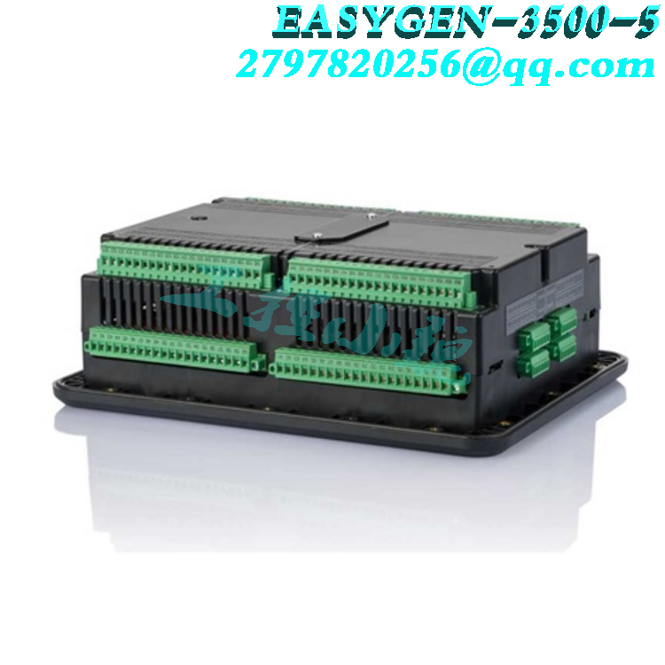
The Woodward easYgen-3500-5/P2 (Part No. 8440-2145) is a marine-specific model within the high-end easYgen-3000 series generator set controller line from Woodward, Inc. (USA), featuring the P2 package configuration (Co-Gen / CHP). Designed specifically for marine power systems, this product integrates core functions such as engine operation control, generator protection, automatic synchronization, active/reactive load sharing, and multi-unit Power Management System (PMS) capabilities. It serves as a critical control unit for marine main power stations, emergency power stations, and land-based combined heat and power (CHP) systems.
This model has obtained type approval from major classification societies—including LR (Lloyd’s Register), ABS (American Bureau of Shipping), DNV, GL (Germanischer Lloyd), and BV (Bureau Veritas)—and holds multiple international certifications such as UL, cUL, CE, CSA, and EAC. It meets the requirements for long-term, reliable operation in harsh marine environments characterized by salt spray, vibration, and heat/humidity.
II. Operating Principle
2.1 System Architecture
The easYgen-3500-5/P2 utilizes a microprocessor-based, distributed peer-to-peer control architecture. Each generator set is equipped with a controller, and the controllers communicate at high speed via a CANopen bus or redundant Ethernet (Ethernet B/C), enabling parallel operation and automatic load sharing for up to 32 generator sets without the need for a host master station.2.2 Core Control Process
The controller’s operation involves the following key stages:
1) Data Acquisition
Real-time acquisition of generator-side three-phase voltage and current (Class 1 accuracy)
Acquisition of busbar voltage (three-phase synchronous measurement; a feature specific to the P2 version)
Acquisition of engine speed (via MPU magnetic pickup or ECU/J1939 interface)
Acquisition of analog signals such as temperature, pressure, and oil level (via configurable FlexIn inputs)
2) Engine Start/Stop and Speed Control
Executes pre-lubrication, starting, warm-up, and grid-parallel loading sequences according to preset timing
Controls engine throttle via a PID governor to regulate frequency and active power
Supports various prime movers, including diesel engines, gas engines, and gas turbines
3) Automatic Synchronization and Grid Paralleling
Real-time monitoring of voltage, frequency, and phase angle differences between the incoming generator and the busbar
Automatically adjusts engine speed (acceleration/deceleration) and generator voltage (via AVR excitation bias output)
Issues a circuit breaker closing command when conditions are met, achieving bumpless grid paralleling
Supports multiple synchronization strategies, such as slip synchronization, phase angle matching, and run-up synchronization
4) Load Sharing and Power Management
Automatically distributes active power (kW) and reactive power (kvar) according to preset ratios during parallel operation
Automatically starts and stops generator sets based on load fluctuations (staged loading/unloading)
Implements peak/valley regulation and grid-parallel operation… Off-grid switching; import/export power control
Supports soft loading and soft unloading for bumpless transfer
5) Protection and Alarms: Built-in comprehensive generator protection functions compliant with ANSI standards:
Overvoltage (59), Undervoltage (27)
Over-frequency (81O), Under-frequency (81U)
Reverse power (32R), Low power (32F)
Instantaneous overcurrent (50), Time-delayed overcurrent (51)
Unbalanced load (46), Ground fault (51G)
Synchro-check (25)
III. Product Advantages
3.1 Highly integrated, multi-functional unit
The easYgen-3500-5/P2 integrates functions—such as engine speed control, generator excitation bias, synchronization control, protection relaying, and power management—that previously required multiple independent devices into a single unit. This significantly reduces the number of cabinet components, wiring workload, and potential points of failure. 3.2 Marine-grade reliability design
Wide operating temperature range: -40°C to +70°C, suitable for extreme engine room temperatures
Vibration, salt spray, and moisture resistance: Complies with marine classification society environmental testing requirements
Direct 690 V AC connection: Voltage measurement inputs require no external PTs, simplifying wiring
No derating up to 4,000 meters altitude: Suitable for various ocean-going and inland vessels
3.3 Redundant communication ensuring power plant safety
Supports dual-channel Ethernet redundancy (Ethernet B / C)
CANopen bus connects up to 16 LS-5 / LS-6XT circuit breaker control modules
Controller reverts to standalone mode during communication network failures without interrupting basic power supply
3.4 Flexible I/O configuration and programmable logic
10 configurable discrete inputs; up to 12 programmable logic outputs (LogicsManager™)
4 FlexIn™ configurable analog inputs (settings include 0–10V, 0–20mA, Pt100, RTD, etc.)
P2 version offers additional three-phase synchronized busbar voltage measurement and phase sequence monitoring
Users can freely define I/O functions and control logic via ToolKit software; no external PLC required
3.5 Powerful event logging and diagnostic capabilities
300-event log with real-time clock (battery-backed)
Records operating hours, start counts, and maintenance intervals
Front-panel LCD Real-time display of parameters such as voltage, current, power, frequency, and power factor
Supports multi-language interfaces (including Chinese, English, Spanish, Russian, French, Japanese, etc.)
3.6 Standardized configuration for easy maintenance
Uses Woodward ToolKit™ software for unified parameter configuration and commissioning
Supports offline editing and parameter block export/import
Firmware can be upgraded on-site via USB or Ethernet
High interchangeability of spare parts within the series reduces inventory costs
IV. Impact on the Marine and Power Industries
4.1 The “brain” of marine main and emergency power stations
In modern marine power systems, the easYgen-3500-5/P2 serves as the core control unit for each generator set. It is responsible for:
Ensuring balanced power distribution during the parallel operation of multiple generator sets
Rapidly adjusting generator output during heavy-load startups (e.g., ballast pumps, steering gear, thrusters)
Automatically starting the emergency generator set (AMF) upon loss of main power to ensure a supply to critical equipment
4.2 Enhancing the safety and economic efficiency of shipboard power plants
Precise reverse-power and overcurrent protection effectively prevents damage to generator windings
Automatically starting or stopping generator sets based on load demand, avoiding fuel waste caused by “oversized equipment for light loads”
Soft loading/unloading functions minimize the impact of circuit breaker operations on the electrical grid and extend equipment lifespan
4.3 Suitable for various vessel types
Bulk carriers, container ships, oil tankers: Parallel control of multiple generator sets in the main power plant
Offshore support vessels (OSV), drilling platforms: Power plant management within Dynamic Positioning (DP) systems
Luxury cruise ships, Ro-Pax ferries: Power distribution management for multi-section busbars requiring high reliability
Fishing vessels, engineering vessels: Automated power plant systems for single or dual generator sets
4.4 Extended applications in land-based sectors
Beyond marine applications, this controller is also widely used in:
Data center backup power (AMF automatic transfer)
Industrial park Combined Heat and Power (CHP / Co-Gen) systems
On-site power plants for mines and oilfields
Distributed power generation systems for islands and reefs
V. Operation Methods
5.1 Operating Modes
The controller’s front panel offers four operating modes, selectable via the mode button or remote signals:
Table
| Mode | Function Description |
| — | — |
| STOP | Unit stopped; circuit breaker open; monitoring only, no control actions performed |
| MANUAL | Operator manually controls unit start/stop, circuit breaker closing/opening, and voltage/frequency adjustment |
| AUTO | Fully automatic mode: automatically starts/stops the unit, synchronizes to the grid, and distributes load based on busbar status and load demand |
| TEST | On-load/no-load test mode for periodic maintenance testing; does not affect normal grid power supply |
5.2 Basic Start-up Operation (Manual Mode)
Confirm that the control power supply (DC 24V or AC 85–265V) is normal and the LCD shows no critical alarms
Switch the operating mode to MANUAL
Press the Start button; the controller executes pre-lubrication → starter motor engagement → warm-up sequence
Once the unit reaches rated speed, verify that voltage and frequency are normal
Press the GCB (Generator Circuit Breaker) close button (for standalone operation)
After applying the load, check power distribution via the front panel or ToolKit
5.3 Automatic Mode (AUTO) Operation
Confirm that all protection parameters are correctly configured
Switch the mode to AUTO
The controller responds automatically based on pre-programmed logic:
Busbar power loss → automatic unit start → voltage build-up → Circuit Breaker Closing
Load rises above the set threshold → Automatically start the next generator unit → Synchronize and connect to the grid → Share the load
Load decreases → Automatically shed load → Disconnect from the grid → Shut down and cool down
5.4 Parameter Configuration (ToolKit Software)
Install Woodward ToolKit configuration software on the PC
Connect to the controller via USB cable, Ethernet, or CAN interface
Enter online mode or the offline editor to set key parameters:
Generator rated voltage, rated current, and PT/CT transformation ratios
Protection settings (over/undervoltage percentage, overcurrent multiplier, reverse power value)
Synchronization parameters (allowable voltage, frequency, and phase angle differences)
Governor and AVR PID parameters
Start/stop sequence, load grouping, and priority settings
Save the configuration file (.wset format) and back it up locally
VI. Installation and Usage Precautions
6.1 Installation Environment Requirements
Install away from sources of strong electromagnetic interference (e.g., variable frequency drives, high-power transformers)
Ensure sufficient space above and below for wiring and heat dissipation (recommended minimum: 50 mm)
Ensure the gasket is intact during panel mounting to prevent condensation ingress
In marine engine rooms, avoid exposure to direct dripping water or oil mist corrosion
6.2 Electrical Wiring Precautions
Do not use 120 V and 480 V inputs simultaneously for voltage measurement …two sets of terminals; otherwise, measurement errors or damage to the device may occur.
It is recommended to install a slow-blow fuse to protect the voltage measurement circuit.
The secondary side of the current transformer (CT) must never be left open-circuit; the CT secondary terminals must be short-circuited before wiring.
The battery charger must be turned off before removing or installing the battery; otherwise, the control device may be damaged.
Power cables and signal cables must be routed separately, with a minimum parallel spacing of 200 mm.
6.3 Parameter Setting Precautions
Incorrect PT ratio settings can lead to abnormal AVR excitation bias output, potentially causing over-voltage or under-voltage shutdowns (pay special attention to AVR regulation issues when the PT ratio is not 1, particularly in manual mode).
Protection setpoints must be configured strictly in accordance with the generator nameplate specifications and classification society rules; they must not be relaxed arbitrarily.
All units operating in parallel must be configured with identical communication addresses, baud rates, and load-sharing parameters.
After modifying critical parameters, actual integrated system tests must be performed to verify correct operation logic.
6.4 Routine Maintenance Points
Periodically (recommended every six months) review event logs and alarm history to analyze abnormal trends.
Check the brightness of the front display screen and the tactile response of the buttons.
Verify the reliability of safety circuits, such as the emergency stop button and mechanical overspeed protection.
It is recommended to replace the backup battery (lithium battery for clock backup) every 3–5 years.
Periodically conduct no-load and load tests to ensure reliable operation of protection functions.
6.5 Troubleshooting Common Issues
Failure to synchronize/connect to the grid: Check voltage difference, frequency difference, phase sequence, and synchronization tolerance settings.
Uneven load sharing: Check PID parameters, CT/PT transformation ratios, communication connections, and droop settings.
Frequent alarm shutdowns: Review event logs to identify specific trigger conditions and check sensor wiring.
Communication loss: Check CAN bus terminal resistors (120Ω), Ethernet cables, and address conflicts.
VII. Summary
As a high-end generator set controller for marine power systems, the Woodward easYgen-3500-5/P2 (8440-2145) has become a mainstream choice for multi-unit parallel control in ocean-going vessels, offshore engineering platforms, and land-based captive power plants, thanks to its highly integrated functionality, comprehensive marine classification society certifications, redundant communication architecture, and flexible programmability. A proper understanding of its operating principles, adherence to standardized operating procedures, and strict compliance with installation and maintenance requirements are key to ensuring the long-term safe, economical, and reliable operation of the marine power plant.
More model recommendations:
WOODWARD easYgen-3000
WOODWARD easYgen-1500
WOODWARD easYgen-3500XT
WOODWARD easYgen-3500
WOODWARD easYgen-100
WOODWARD EASYGEN-1000
WOODWARD EASYGEN-320
woodward EASYGEN-3500-5/P2 8440-2145
woodward EASYGEN-3500-5/P2 8440-2145
ABB 3BHE023681R0102
ABB 3BHE023682P201
ABB 5SGY3545L0010
WOODWARD 8256-008
WOODWARD 8576-449
WOODWARD 8561-301
WOODWARD 8561-697
5437-1067A-TMR Kernel
5437-523 Woodward
5466-258 Woodward
5466-318-TMR Kernel
8200-1300 WOODWARD
8200-1300-Woodward
8200-1302 WOODWARD
8200-150 WOODWARD
8200-1502 Woodward
8270-768 WOODWARD
8440-1934 WOODWARD
8440-2050 Woodward
8440-2222 Woodward
WOODWARD 9907-205
WOODWARD 9907-018
WOODWARD 9907-163
woodward 9907-163
WOODWARD 9907-175
woodward 9907-149
woodward 9907-162
woodward 9907-164
woodward 9907-165
woodward 9907-167
5466-1146 Woodward
5466-1145 Woodward
5466-1141 Woodward
5466-1115 Woodward
5466-1105 Woodward
5466-1051 Woodward
5466-1050 Woodward
5466-1049 Woodward
5466-1047 Woodward
5466-1046 Woodward
More……
admin –
Real-time monitoring of voltage, frequency, and phase angle differences between the incoming generator and the busbar
Automatically adjusts engine speed (acceleration/deceleration) and generator voltage (via AVR excitation bias output)
Issues a circuit breaker closing command when conditions are met, achieving bumpless grid paralleling
Supports multiple synchronization strategies, such as slip synchronization, phase angle matching, and run-up synchronization