
Description
Many products have not yet been listed online; please contact us for more information.
If the product model differs from the displayed image, the model number takes precedence. Please contact us for specific product photos; we can arrange for warehouse staff to take and send confirmation images.
We operate 76 shared warehouses globally, so it may sometimes take a few hours to provide an accurate response; we appreciate your understanding. Rest assured, we will address your inquiries as quickly as possible.
I. Product Overview
The easYgen-3500XT is a next-generation generator set controller from Woodward and the flagship model of the easYgen-3000XT series. Designed as an integrated power management controller for complex paralleling applications, it replaces the previous easYgen-3000 series, offering significant improvements in hardware interfaces, communication capabilities, measurement accuracy, and system scalability.
The easYgen-3500XT is available in two hardware configuration packages:
P1 Package (Complex Paralleling Model): Designed for complex paralleling applications, it features redundant Ethernet communication, connectivity for LS-5 circuit breaker controllers, and a standard I/O configuration.
P2 Package (CHP Model): Building on the P1 package, this version expands onboard I/O capacity and adds three-phase busbar voltage measurement and phase sequence monitoring. It is suitable for Combined Heat and Power (CHP) applications and scenarios requiring extensive analog signal acquisition.
Additionally, for outdoor low-temperature environments, the easYgen-3500XT offers an LT (Low Temperature) version capable of operating in temperatures as low as -40°C.
2. Working Principle
2.1 Signal Acquisition and Measurement Layer
The easYgen-3500XT utilizes built-in measurement circuitry to acquire electrical parameters from the generator and busbar sides in real-time, including three-phase voltage, three-phase current, frequency, active power, reactive power, power factor, and energy metering. Measurements are based on True RMS values; power measurement accuracy meets Class I (Class 1.0) standards, while voltage and current measurement accuracy meets Class 0.5 standards. The controller supports direct connection to voltage levels up to 690 VAC, enabling primary-side voltage sampling without the need for external voltage transformers.
Simultaneously, the controller acquires engine speed signals via speed sensors (magnetic pickup or switch-type) and directly reads analog data—such as coolant temperature, oil pressure, oil temperature, and fuel level—transmitted by the engine ECU over the CAN bus (J1939 protocol), thereby achieving comprehensive monitoring of the engine’s operating status.
2.2 Control and Protection Layer
The controller incorporates various protection algorithms and configures generator and system protection functions in accordance with ANSI standards, primarily including:
Generator Protection: Over/Under-voltage (ANSI 59/27), Over/Under-frequency (ANSI 81O/81U), Reverse Power (ANSI 32R), Overpower (ANSI 32), Instantaneous Overcurrent (ANSI 50), Definite-time Overcurrent (ANSI 51/51V), Earth Fault (ANSI 50G), Synchro-check (ANSI 25), and Power Factor Protection (ANSI 55).
Grid/Busbar Protection: Over/Under-voltage, Over/Under-frequency, Synchro-check, and Phase Sequence Monitoring (supported by the P2 version). Engine Protection: Protection trips—such as for high coolant temperature, low oil pressure, overspeed, and start failure—based on J1939 data and discrete inputs.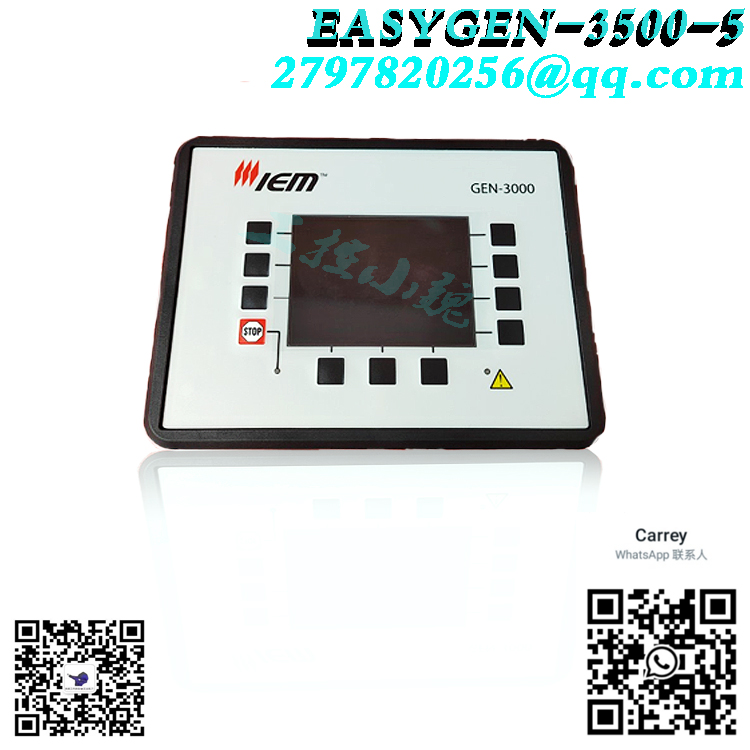
When a protection event is triggered, the controller outputs a relay signal to trip the generator circuit breaker (GCB) or bus circuit breaker, isolating the fault and ensuring equipment safety.
2.3 Synchronization and Paralleling Layer
When multiple generator sets need to operate in parallel, the easYgen-3500XT executes an automatic synchronization procedure. It monitors the voltage, frequency, and phase differences between the incoming unit and the live bus in real-time. By adjusting engine speed (via the speed control output) and generator excitation (via the voltage control output) to meet synchronization criteria, it issues a command to close the generator circuit breaker.
Once paralleling is complete, the controller enters load-sharing mode. It supports two load-sharing strategies:
Droop Control: Each unit automatically distributes active and reactive loads based on its capacity ratio; basic paralleling is achieved without the need for high-speed communication lines.
Isochronous / Load Share Control: Load information is exchanged between units via CAN bus or redundant Ethernet to achieve precise, isochronous load sharing and maintain system frequency and voltage stability.
2.4 Communication and System Management Layer
The easYgen-3500XT is equipped with up to nine communication ports, including three Ethernet ports (Modbus TCP), three CAN ports (supporting CANopen and J1939), one RS-485 serial port (Modbus RTU), one USB debugging port, and one expansion slot. Through these interfaces, the controller can communicate within a network comprising supervisory control systems, PLCs, remote panels, and circuit breaker controllers (LS-5/LS-6XT).
In large-scale systems, the easYgen-3500XT can operate in conjunction with the Woodward GC-3000XT master controller to enable centralized management and automatic scheduling of up to 496 generator sets.
III. Core Technical Advantages
Integrated Design: Combines engine control, generator protection, automatic synchronization, load sharing, and power management into a single unit, reducing the need for external control cabinets and complex wiring.
High-Capacity Paralleling Capability: A single controller manages the parallel operation of up to 32 generator sets; when combined with a group control system, this expands to 496 units, covering applications ranging from small backup power stations to large-scale distributed energy plants.
Redundant Communication Architecture: Supports Ethernet A/B/C triple-port redundancy for load sharing and dual-channel CAN bus communication, ensuring that a failure in any single communication link does not disrupt system paralleling or power management.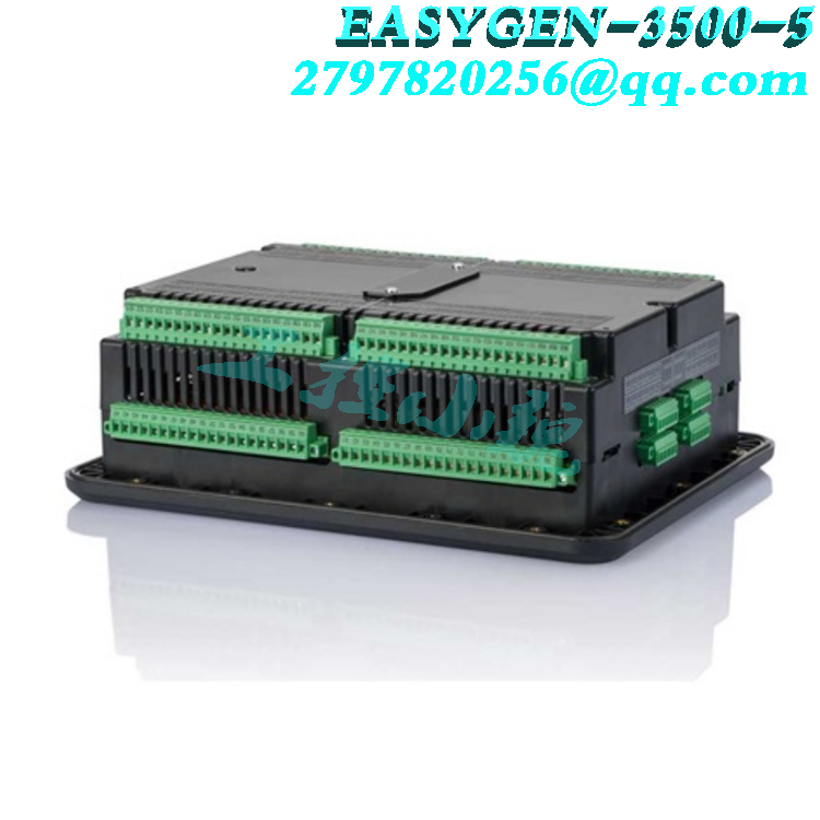
High-Precision Electrical Measurement: Features three-phase True RMS measurement with Class I power accuracy and 0.5-class voltage/current accuracy, providing a reliable data foundation for protection operations and energy management.
Wide Environmental Adaptability: Standard models operate between -20°C and +70°C, while LT (low-temperature) models support -40°C to +70°C; operates without derating at altitudes up to 4,000 meters, making it suitable for field operations and harsh industrial environments.
Direct Wide-Voltage Input: Supports direct sampling of 100 VAC and 400/600 VAC (compatible with systems up to 690 VAC), eliminating the need for numerous voltage transformers found in conventional designs and thereby reducing costs and potential points of failure.
Direct Connection to Multi-Brand Engines: Native support for J1939 communication with ECUs from major engine manufacturers—such as MTU, Volvo, Scania, Cummins, Deutz, MAN, and SISU—enabling plug-and-play functionality. Extensive I/O and Programmable Logic: The P2 version offers 23 digital inputs, 22 digital outputs, 10 analog inputs, and 6 analog outputs, featuring built-in LogicManager programmable logic and three configurable PID controllers.
IV. Application Industries and System Functions
Acting as the “brain” of the generator set system, the easYgen-3500XT plays a critical role in the following industries and scenarios:
Data centers
Industrial parks
Hospitals/hospital complexes
Commercial buildings
Combined Heat and Power (CHP)
Marine and offshore
Mining and oilfields
Distributed energy stations
Rental power generation
4.1 Standby Power and Automatic Mains Failure (AMF)
In facilities requiring high power continuity—such as data centers, hospitals, and financial centers—the easYgen-3500XT monitors mains power status in real-time. Upon a mains failure, the controller automatically starts the standby generator set within seconds, handling voltage buildup, synchronization, and breaker closure to supply critical loads. Once mains power is restored, it automatically executes soft unloading, breaker opening, and a cool-down shutdown sequence to switch back to the mains supply. Its core function is to ensure uninterrupted power for critical loads.
4.2 Combined Heat and Power (CHP / Distributed Energy)
In settings such as industrial parks and district energy stations, generator sets not only generate electricity but also recover waste heat from jacket water and exhaust gases for heating or cooling applications. The P2 version of the easYgen-3500XT features built-in analog expansion interfaces and configurable PID controllers. It can directly control process variables such as heating circuit temperatures and water levels, enabling the optimized, synergistic operation of electric and thermal systems to enhance overall energy efficiency.
4.3 Grid Parallel Operation and Peak Shaving (Import/Export / Peak Shaving)
When operating in parallel with the public grid, the easYgen-3500XT can operate based on preset power factor or active power setpoints, enabling reverse power flow (selling electricity to the grid) or peak shaving (generating power on-site to reduce grid purchases during peak load periods). The controller supports base-load operation, import/export power control, and unbalanced load management, helping users optimize electricity costs and participate in grid demand response programs.
4.4 Islanding and Multi-Unit Parallel Power Supply
In areas without grid coverage—such as mines, oil fields, and remote camps—multiple generator sets can be paralleled using the easYgen-3500XT to form an independent power grid. The controller automatically determines the number of units to start or stop based on the total load (load-dependent start/stop) and economically distributes the load among running units, enabling efficient, unattended operation of an independent microgrid.
4.5 Marine and Offshore Applications
The easYgen-3500XT holds type approvals from ABS (American Bureau of Shipping) and LR (Lloyd’s Register), meeting requirements for vibration, temperature/humidity, and electromagnetic compatibility in marine environments. In shipboard power plants, it manages the paralleling, load sharing, and protection of diesel generator sets, ensuring reliable power supply during navigation, port stays, and emergency situations.
5. Operation Methods
5.1 Operating Modes
The easYgen-3500XT offers four basic operating modes, which can be switched via front-panel buttons or external discrete inputs:
Auto Mode (AUTO): The controller automatically executes start, synchronization, paralleling, load sharing, unloading, and shutdown sequences based on preset logic; this is the recommended mode for normal operation.
Manual Mode (MANUAL): Operators manually control the unit’s start, breaker closing/opening, and shutdown via the panel; this mode is used for commissioning and maintenance.
Stop Mode (STOP): The unit performs a normal shutdown sequence and remains in the stopped state, ignoring external start commands.
Test Mode (TEST): Used for on-load testing. The unit starts and runs under load but does not automatically switch to mains power; this facilitates periodic performance checks without interrupting power supply to critical loads.
5.2 Front Panel Operation
The easYgen-3500XT front panel features an LCD display and tactile buttons. During normal operation, the main screen displays generator voltage, current, frequency, power, accumulated energy, and operating status. Buttons allow the user to navigate through screens to view busbar parameters, engine data, alarm records, and event logs.
The display-less version (easYgen-3400XT) can be used in conjunction with the RP-3000XT remote touchscreen panel to achieve the same monitoring and control functions.
5.3 Software Configuration
Controller parameter configuration is performed using Woodward ToolKit software. Supported connection methods include direct USB, Ethernet (Modbus TCP / ServLink), or CAN bus. ToolKit provides a graphical configuration interface for setting protection setpoints, synchronization parameters, load sharing curves, I/O definitions, communication parameters, and logic control programs. Configuration files can be uploaded, downloaded, backed up, and archived, facilitating batch replication to identical units.
5.4 Remote Monitoring
Using Modbus TCP/RTU protocols, the easYgen-3500XT can connect to SCADA systems or host computers to enable remote data acquisition and control. Users can monitor the operating status of each unit, adjust power setpoints, execute remote start/stop commands, and receive alarm notifications from the central control room.
VI. Installation and Usage Precautions
6.1 Electrical Wiring Precautions
The controller operates on a 12/24 VDC power supply (permissible range: 8–40 VDC); verify the correct voltage and polarity before wiring to prevent equipment damage caused by reverse connection.
Voltage sensing circuits connect directly to generator and busbar voltages (up to 690 VAC); strictly adhere to high-voltage safety protocols and ensure power is disconnected before performing wiring work.
Operation with an open-circuited current transformer (CT) secondary is strictly prohibited; short-circuit the CT secondary terminals before connecting or disconnecting wires.
Use shielded twisted-pair cable for speed sensor (MPU) wiring, with the shield grounded at one end only; route the cable away from power cables to avoid interference with speed measurement.
Route communication cables (CAN, Ethernet) separately from power cables, maintaining a minimum separation of 200 mm; use metal partitions for isolation if necessary.
6.2 Installation Environment Requirements
The standard model operates within a temperature range of -20°C to +70°C; for installation in unheated outdoor enclosures, select the LT low-temperature model (-40°C to +70°C).
Ambient humidity must be below 95% with no condensation. In high-humidity environments, measures such as in-cabinet heating for dehumidification must be implemented.
The front panel ingress protection rating is IP66 (screw-mounted) or IP54 (clip-mounted), while the rear wiring compartment is rated IP20. Ensure the front sealing gasket is intact during cabinet door installation.
The device should be installed in a location with minimal vibration and away from intense heat sources, such as engine exhaust manifolds.
6.3 Commissioning and Operation Precautions
Before powering up for the first time, verify that all protection settings (over-voltage, under-voltage, over-frequency, under-frequency, over-current, etc.) match the parameters of the generator being protected to prevent false tripping or failure to trip.
During initial commissioning for paralleling, observe the synchronization process in manual mode first; switch to automatic mode only after confirming that the phase, frequency, and voltage synchronization logic is functioning correctly.
Terminating resistors must be correctly installed at both ends of the load-sharing communication line (CAN load-sharing line); failure to do so may result in unstable load sharing or data packet loss.
Always back up the current configuration file before upgrading the controller firmware; do not disconnect power during the upgrade process, as this could render the device inoperable (“brick” it).
Regularly back up controller parameters and event logs; it is recommended to export and archive the configuration every six months.
Safety Warning
This device involves high-voltage electrical circuits and engine control. All installation, wiring, commissioning, and maintenance work must be performed by qualified electrical engineers in strict accordance with the official Woodward installation manual and on-site safety regulations. Never open the wiring compartment cover or touch internal terminals while the device is powered.
6.4 Routine Maintenance Recommendations
Periodically check that the front panel display is functioning correctly and that button responses are responsive. Check the tightness of terminal connections quarterly, paying particular attention to terminals in high-current circuits (such as those for current sampling and power supply).
Periodically export alarm and event logs to analyze abnormal trends and identify potential issues in advance.
Keep the equipment clean; wipe the front panel with a dry, soft cloth, and do not use organic solvents.
Model recommendation:
8440-1800
8440-1925
8440-1934
8440-1546
8440-1894
8440-2096
8440-2077
8440-1809
8440-2050
8440-1878
More……
admin –
Industrial Control Sales Consultant: Carrey welcomes customers to comment and contact us to inquire about the status of this module.
zoritoler imol –
I have been surfing online greater than 3 hours today, yet I never found any interesting article like yours. It is lovely price enough for me. Personally, if all website owners and bloggers made excellent content material as you did, the web shall be a lot more helpful than ever before. “Where facts are few, experts are many.” by Donald R. Gannon.
smorter giremal –
I like what you guys are up too. Such smart work and reporting! Keep up the excellent works guys I have incorporated you guys to my blogroll. I think it will improve the value of my website 🙂
zoritoler imol –
Generally I do not read article on blogs, but I wish to say that this write-up very forced me to try and do so! Your writing style has been amazed me. Thanks, quite nice post.
tlovertonet –
Heya i’m for the first time here. I came across this board and I find It really useful & it helped me out a lot. I hope to give something back and help others like you helped me.
Alla Kapur –
Excellent read, I just passed this onto a colleague who was doing some research on that. And he actually bought me lunch as I found it for him smile Thus let me rephrase that: Thank you for lunch! “Life is a continual upgrade.” by J. Mark Wallace.
Garland Goodermote –
Thank you for the auspicious writeup. It in fact was a amusement account it. Look advanced to more added agreeable from you! However, how can we communicate?
Ula Hunziker –
I got what you mean , regards for putting up.Woh I am pleased to find this website through google.
fdertol mrtokev –
Hi there! This is kind of off topic but I need some guidance from an established blog. Is it hard to set up your own blog? I’m not very techincal but I can figure things out pretty fast. I’m thinking about setting up my own but I’m not sure where to start. Do you have any ideas or suggestions? Cheers
admin –
Installation and Usage Precautions
6.1 Electrical Wiring Precautions
The controller operates on a 12/24 VDC power supply (permissible range: 8–40 VDC); verify the correct voltage and polarity before wiring to prevent equipment damage caused by reverse connection.
Voltage sensing circuits connect directly to generator and busbar voltages (up to 690 VAC); strictly adhere to high-voltage safety protocols and ensure power is disconnected before performing wiring work.
Operation with an open-circuited current transformer (CT) secondary is strictly prohibited; short-circuit the CT secondary terminals before connecting or disconnecting wires.
Use shielded twisted-pair cable for speed sensor (MPU) wiring, with the shield grounded at one end only; route the cable away from power cables to avoid interference with speed measurement.
Route communication cables (CAN, Ethernet) separately from power cables, maintaining a minimum separation of 200 mm; use metal partitions for isolation if necessary.
6.2 Installation Environment Requirements
The standard model operates within a temperature range of -20°C to +70°C; for installation in unheated outdoor enclosures, select the LT low-temperature model (-40°C to +70°C).