
Description
Many products have not yet been listed online; please contact us for more information.
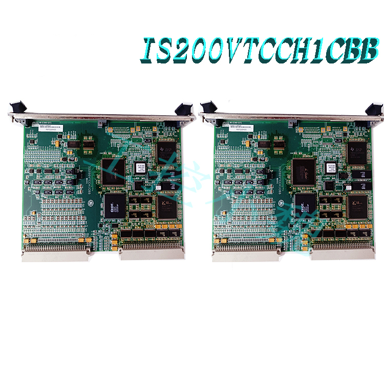
If the product model differs from the displayed image, the model number takes precedence. Please contact us for specific product photos; we will arrange for warehouse staff to take and verify them.
We operate 76 shared warehouses globally, so it may sometimes take a few hours to provide you with an accurate response; we appreciate your understanding. Rest assured, we will address your inquiries as quickly as possible.
151X1207BA10SA01 Other Names:
EX2100 Module 151X1207BA10SA01
151X1207BA10SA01 Turbine Control Unit
Input/Output Unit 151X1207BA10SA01
I. Product Overview
The 151X1207BA10SA01 fan module is part of the hardware architecture of the GE EX2100 excitation system and is a forced-air cooling unit custom-developed for excitation power cabinets. This module integrates an industrial-grade drive motor, a centrifugal fan impeller, mounting structures, electrical interfaces, and protective components. It undergoes comprehensive calibration and performance testing prior to shipment and is designed to fit directly into the mounting slots and air duct interfaces of the EX2100 series power cabinets. It provides precise, efficient cooling for high-heat components—such as thyristor rectifier bridges, snubber circuits, and power resistors—serving as a critical component for ensuring the long-term, reliable operation of the excitation system.
II. Core Operating Principles
This fan module operates on the principle of forced-convection air cooling, utilizing the EX2100 system’s temperature control logic to achieve closed-loop thermal management. The complete operational workflow is as follows:
Airflow Generation and Directional Delivery: Upon energization, an industrial-grade drive motor spins the centrifugal fan impeller at high speed, creating negative pressure at the intake to draw cooler ambient air from outside the cabinet into the module. Through a customized air duct design, the airflow is directed onto the heat sink fins of the power components, creating a high-speed, uniform sweeping effect that covers all critical heat-generating zones.
Heat Exchange and Exhaust: The cool airflow makes full contact with the hot heat-dissipating surfaces, removing Joule heat and circuit loss heat generated by the components via convective heat transfer. The heated air is then exhausted into the external environment through the cabinet’s designated air ducts, completing a single cooling cycle and maintaining the internal temperature within the rated operating range.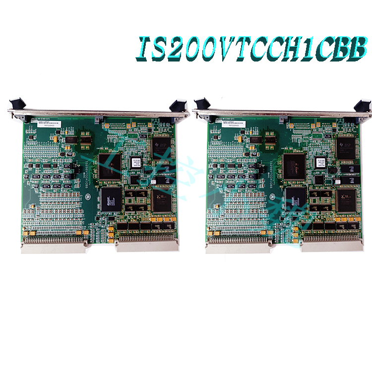
Intelligent Temperature Control and Redundancy Switching: Integrated with the EX2100 system’s temperature monitoring and control logic, the module automatically manages start/stop operations and adjusts fan speeds based on real-time feedback from internal temperature sensors, thereby minimizing operating losses while meeting cooling requirements. In a primary/standby redundancy configuration, the system automatically switches to the backup fan in the event of a primary fan failure and issues an alarm signal, preventing overheating-induced shutdowns caused by cooling interruptions.
III. Product Technical Advantages
1. OEM Integrated Modular Design for High O&M Efficiency
This module features an integrated design from the original manufacturer (GE), combining the drive system, airflow structure, wiring terminals, and protective components into a single, replaceable unit that requires no on-site assembly or commissioning. The unit allows for rapid, complete replacement in the event of a failure, significantly reducing maintenance downtime for the excitation system and enhancing the availability and operational cost-efficiency of the generator set.
2. High-reliability industrial-grade configuration for harsh operating conditions
Utilizes industrial-grade motors compliant with electric power industry standards, featuring high insulation ratings and robust electromagnetic interference (EMI) immunity to withstand the intense electromagnetic environment within the excitation system. A wide operating temperature range accommodates the temperature fluctuations found in power plants and industrial sites, supporting continuous, stable 24/7 operation under rigorous industrial conditions.
3. Customized airflow design for superior heat dissipation efficiency
Fan impeller parameters and air outlet configurations are tailored to the internal component layout and airflow structure of the EX2100 power cabinet. This ensures comprehensive airflow coverage—eliminating dead zones—and precisely targets key heat-generating components such as thyristors and rectifier bridges. Heat dissipation efficiency far exceeds that of general-purpose fans, effectively preventing component aging and performance degradation caused by localized overheating.
4. Seamless system-level compatibility and support for redundant architectures
Integrates seamlessly with the EX2100 excitation system’s temperature control modules, fault detection logic, and status monitoring systems, supporting primary/standby redundant fan configurations. Fault signals are transmitted to the excitation control system in real-time, enabling automatic failover and remote alarming, thereby enhancing the overall availability and fault tolerance of the cooling system.
5. Low-loss aerodynamic design for cost-effective operation
An optimized centrifugal impeller aerodynamic profile minimizes airflow eddy current losses, reducing motor input power while meeting rated airflow and pressure requirements. Additionally, the fan generates minimal heat itself, avoiding any increase in the cabinet’s thermal load; this ensures highly efficient, energy-saving operation and lowers long-term operating costs.
IV. Core Role in Relevant Industries
As a key supporting component of the EX2100 excitation system, the 151X1207BA10SA01 fan module delivers core value by ensuring the system’s reliable operation through stable heat dissipation, thereby supporting production and power supply safety in downstream industries. The core application industries and their respective roles are as follows:
1. Power Generation Industry (Thermal, Hydro, and Gas Turbine Power Plants)
Ensuring stable operation of the generator’s core control unit: The excitation system is the core control unit of a synchronous generator, responsible for regulating terminal voltage and reactive power. The fan module prevents damage to power components caused by overheating through continuous heat dissipation; this averts unplanned generator shutdowns triggered by excitation system trips, thereby ensuring the stability and reliability of grid power supply.
Supporting full-load and dynamic operating conditions: Under conditions such as full-load operation or forced excitation during grid faults, heat generation in the excitation power unit rises sharply. The fan module’s high-performance cooling capability ensures the excitation system can continuously output rated excitation current, meeting the generator’s voltage regulation and grid reactive power support requirements.
Extending equipment lifecycle: Stable temperature control prevents performance degradation of power components caused by thermal shock or high-temperature oxidation. This extends the overall service life of the EX2100 excitation system and reduces long-term operation, maintenance, and equipment replacement costs for the power plant.
2. Industrial Captive Power Plants (Steel, Chemical, Mining)
Industrial captive power plants often face shock-like and fluctuating loads, resulting in frequent changes in excitation system operating conditions and significant fluctuations in heat generation. The fan module’s dynamic cooling capability adapts to thermal load variations caused by load fluctuations, ensuring the continuity and stability of the power supply for industrial production and preventing production line downtime losses caused by power supply failures.
3. Distributed Energy and Combined-Cycle Power Generation
In emerging power generation scenarios—such as gas-steam combined-cycle plants and synchronous generators paired with energy storage systems—equipment undergoes frequent start-stop cycles and significant load-following (peak-shaving) demands, requiring the excitation system to respond rapidly to changing operating conditions. The 151X1207BA10SA01 fan module works with the excitation system to provide rapid start/stop cooling, meeting the operational requirements for flexible peak-load regulation and supporting the stable operation of new energy power systems.
V. Standard Operating Procedures
1. Installation and Wiring
Safety First: Before installation, disconnect the main and control power supplies of the EX2100 power cabinet and execute Lockout/Tagout (LOTO) procedures. Verify that there is no residual voltage inside the cabinet using a voltage tester before commencing work.
Mechanical Installation: Align the fan module with the mounting rails and locating pins inside the cabinet, slide it smoothly into position, and tighten the mounting bolts. Ensure a tight fit between the module and the air duct interface with no gaps that could cause air leakage or airflow short-circuiting.
Electrical Wiring: Refer to the original GE wiring diagrams to connect the fan power circuit and operation status feedback circuit to the corresponding terminal blocks; tighten the terminals and ensure proper insulation. For redundant configurations, clearly distinguish between the primary and backup fan circuits to avoid wiring errors.
2. Startup and Commissioning
Pre-power-up Checks: Ensure the fan inlet and outlet are free of obstructions. Manually rotate the impeller to verify there is no binding or casing contact. Confirm that the wiring phase sequence and voltage level match the equipment nameplate specifications.
Stand-alone Testing: Power up the fan module independently. Verify that the fan rotation direction matches the markings on the unit, there are no abnormal noises or severe vibrations during operation, and the operating current is within the equipment’s rated range.
System Commissioning: Connect the module to the EX2100 control system. Use simulated temperature signals or parameter configurations to verify the automatic start/stop logic, temperature regulation logic, and fault-based switchover logic. Ensure that operating status signals are accurately transmitted to the monitoring interface.3. Daily Operation
Automatic Mode: During normal operation, the fan operates under automatic control. The EX2100 system automatically adjusts the operating status based on cabinet temperature; operators simply monitor parameters—such as fan status, current, and cabinet temperature—via the excitation Human-Machine Interface (HMI).
Manual Operation: If manual intervention is required, switch the local control selector to “Manual” mode and start or stop the fan using the control panel buttons. After the operation is complete, promptly switch back to “Automatic” mode to restore the system’s closed-loop control.
VI. Operation and Maintenance Precautions
1. Safe Operating Procedures
All inspection, maintenance, and replacement tasks must be performed only after the power has been disconnected and the absence of residual charge has been verified. Strictly adhere to electrical safety regulations to prevent electric shock and mechanical injury.
While the fan is running, strictly prohibit inserting hands, tools, or other objects into the air inlets or outlets to avoid personal injury or equipment damage caused by the high-speed rotating impeller.
2. Daily Operation and Maintenance Requirements
Routine Inspections: Conduct daily inspections of the fan’s operating sound and vibration levels to ensure there are no abnormal noises or vibrations. Clean the air inlet dust filter monthly to prevent dust accumulation from clogging the airflow path and reducing heat dissipation efficiency.
Periodic Testing: Test the fan motor’s insulation resistance and operating current quarterly to ensure parameters meet equipment specifications. Perform lubrication maintenance on motor bearings annually in accordance with the manual to extend bearing service life.
Redundancy Testing: Conduct a switchover test involving the backup fan every six months to verify that the backup fan automatically engages in the event of a primary fan failure, ensuring the effectiveness of the cooling system’s redundancy. 3. Operating Environment Requirements
The fan’s operating environment must comply with GE’s original temperature specifications; long-term operation at temperatures exceeding these limits is prohibited. Adequate ventilation must be maintained around the cabinet; stacking debris near air inlets is forbidden to ensure that intake air temperature and airflow meet design requirements.
Avoid long-term operation in environments with high dust levels or corrosive gases. If the site environment is harsh, dust and corrosion protection measures must be upgraded, and accumulated dust inside the fan must be cleaned regularly.
4. Spare Parts Replacement Requirements
When replacing the fan module, prioritize the use of GE original spare parts of the same model (151X1207BA10SA01). Non-original substitutes may lead to issues such as mismatched air ducts, insufficient heat dissipation, or non-compliance with electromagnetic compatibility (EMC) standards, potentially causing system failures.
After replacing the spare part, a load-bearing operation test lasting at least 30 minutes must be conducted. Monitor temperature changes within the power cabinet and confirm that heat dissipation performance meets standards before placing the unit into formal operation.
Recommended related products:
151X1225DF01PC03
151X1225DF01PC03RA
DS3820HSPB
151X1215DC20SA01
151X1215DC21MG01
151X1225DE18PC05
IPU2-MA65490100A-D100789
VEGA VEGASTAB TYPE-570.07 8342-20
VPU-A413310
PUD-2-542829-3A-M8513011
More……


Reviews
There are no reviews yet.