
Description
All products on this website are specialized items subject to fluctuating market prices.
Please refer to the customer service department for specific price quotes, as the listed prices are not final.
Before placing an order, please confirm details such as the model, product specifications, and pricing with customer service.
Please contact customer service for further information regarding available units.
I. Product Overview
The IS420UCSBH4A is a UCSB (Universal Control System Block) core controller within the General Electric (GE) Mark VIe control system series. It serves as a dedicated main control unit designed for gas turbines, steam turbines, and heavy-duty industrial rotating equipment. Equipped with an Intel EP80579 1066MHz high-performance processor and running the QNX Neutrino real-time multitasking operating system, the controller networks with distributed I/O modules via a dedicated IONet industrial Ethernet. It executes core control logic—including speed regulation, load control, start/stop sequencing, and fault protection tripping—acting as the central computing and decision-making unit for the Mark VIe turbine control system. It is widely used in industrial sectors such as power generation, petrochemicals, and offshore engineering, where reliability and real-time performance are critical.
II. Operating Principle
2.1 Hardware Architecture and Computing Core
The IS420UCSBH4A utilizes a distributed hardware architecture without a backplane I/O design; the controller itself does not integrate field I/O interfaces. Instead, the acquisition and output of all process signals are handled by distributed I/O modules, allowing the controller to focus on high-speed logic processing. This design eliminates the single-point-of-failure risk associated with traditional backplane-based controllers at the hardware level. Key hardware specifications include a 1066 MHz Intel EP80579 industrial-grade processor, 256 MB of DDR2 SDRAM, and onboard flash memory for firmware storage. It features multi-port IONet Ethernet interfaces and an RS-232 debug serial port, utilizes a passive, fanless cooling design, and mounts onto standard DIN rails within industrial control cabinets.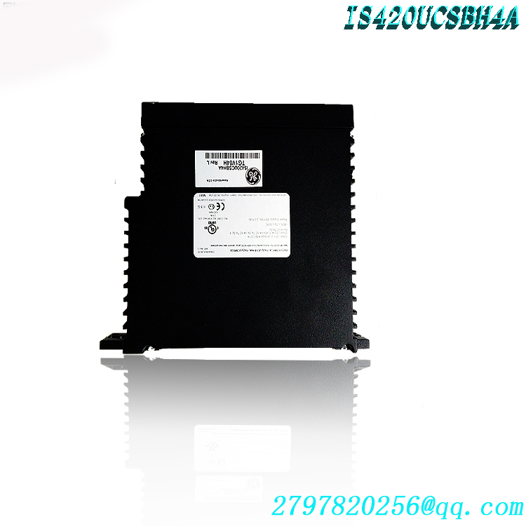
2.2 Real-Time Operating System and Software Execution Mechanism
The controller runs the QNX Neutrino real-time operating system, offering microsecond-level task scheduling responsiveness. It can execute multiple sets of control tasks with varying priorities in parallel without timing deviations. It executes dedicated Mark VIe firmware and function block applications, scanning control logic at fixed intervals. Core algorithms—such as closed-loop speed regulation, load setpoint processing, start/stop sequence control, and protection threshold monitoring—ensure the real-time performance and determinism of control commands, meeting the dynamic control requirements of high-speed rotating equipment.
2.3 IONet Communication and Clock Synchronization Mechanism
The IS420UCSBH4A exchanges data with distributed I/O packs within the system via the dedicated IONet industrial Ethernet. IONet is a proprietary Ethernet network developed by GE specifically for the Mark series control systems; it supports communication exclusively between Mark series controllers and I/O modules, offering high real-time performance, robust security, and strong interference immunity. At the communication layer, it employs the IEEE 1588 PTPv2 Precision Time Protocol, achieving clock synchronization accuracy of ±100 microseconds between the controller and all I/O modules. This ensures temporal consistency across multi-node signal acquisition and control outputs, preventing control errors and nuisance trips caused by timing deviations. 2.4 Complete Control Logic Execution Process
Signal Acquisition Phase: Distributed I/O modules collect analog and discrete signals from field sensors and transmitters. After signal filtering and analog-to-digital conversion, the data is transmitted in real-time to the controller via IONet.
Logic Processing Phase: The controller reads input signals based on a preset scan cycle and executes control algorithms—such as PID regulation, sequence control, protective interlocking, and unit optimization—to generate precise control output commands.
Command Issuance Phase: Calculation results are sent via IONet to the corresponding I/O modules, where they are converted into field signals to actuate devices such as valves, servo mechanisms, and relays.
Status Feedback Phase: The controller simultaneously acquires equipment operating status and fault signals, triggering appropriate alarms or protective trip logic, while uploading operating data and alarm information to the supervisory monitoring system.
2.5 Redundant System Operating Principle
The IS420UCSBH4A supports three deployment modes: simplex, dual redundancy, and TMR (Triple Modular Redundancy). In a redundant configuration, all I/O networks connect to every controller simultaneously; each controller receives all input data and executes calculations in sync. If the primary controller experiences a hardware failure or software anomaly, or requires maintenance shutdown, the standby controller performs a bumpless switchover in less than 50ms. This process ensures no loss of process input data, prevents system downtime caused by single-point failures, and guarantees production continuity.
III. Core Technical Advantages
3.1 High-Speed Real-Time Computing Capability
Equipped with an industrial-grade dedicated processor and the QNX real-time operating system, the control logic scan cycle operates at the millisecond level. It precisely meets the dynamic control requirements of equipment such as gas turbines and high-speed compressors, ensuring high control accuracy and rapid response for critical parameters like rotational speed, pressure, and temperature, while effectively handling complex scenarios such as shock loads and rapid operating condition transitions. 3.2 High-Reliability Redundant Architecture
Supports dual-controller and triple-modular redundancy configurations; hardware-level redundancy switchover takes less than 50ms, ensuring truly bumpless transfer. A fully distributed I/O architecture eliminates the risk of single-point backplane failure, allowing the I/O network to maintain data acquisition capabilities even during controller maintenance shutdowns. Combined with a redundant power supply design, this significantly enhances overall system availability, meeting the high-reliability demands of continuous industrial production.
3.3 Adaptability to Harsh Industrial Environments
Features a passive, fanless cooling design with no moving or wear-prone parts, and offers vibration resistance up to 5g (10–500Hz). It operates within a temperature range of -30°C to +65°C (storage: -40°C to +85°C) and supports humidity levels of 5%–95% (non-condensing). With strong electromagnetic interference (EMI) immunity and compliance with industrial EMC standards, it ensures stable, long-term operation in harsh industrial environments such as steam turbine workshops, petrochemical plants, and offshore platforms.
3.4 Flexible Integration and Expansion Capabilities
Allows for the flexible expansion of various I/O modules via IONet, supporting signal types such as analog, digital, pulse, and RTD/thermocouple inputs. Dedicated gateways enable connectivity with mainstream industrial buses and protocols—including PROFIBUS, Modbus, PROFINET, and OPC UA—facilitating data exchange with third-party systems like DCS, SIS, and MES, thereby meeting the diverse requirements of both new projects and the retrofitting of legacy systems. 3.5 Functional Safety Compliance
When used in conjunction with Mark VIeS safety controllers and safety I/O modules, SIL 2 and SIL 3 functional safety loops can be established in compliance with the IEC 61508 functional safety standard. These systems are suitable for control applications involving flammable or explosive media and high-risk rotating equipment, meeting industrial safety compliance requirements and mitigating operational safety risks.
4. Impact and Core Value for Application Industries
4.1 Power Industry: Gas/Steam Turbine Power Generation Control
The IS420UCSBH4A serves as the core control unit for gas turbines, steam turbines, and combined-cycle units in power plants. Its key functions include:
Enabling precise unit speed regulation, automatic load control, and fully automated execution of start-stop sequences, thereby enhancing operational efficiency and grid response speed;
Integrating comprehensive protection and trip logic to monitor critical parameters—such as vibration, temperature, pressure, and flame—in real-time, triggering protection mechanisms within microseconds during abnormal conditions to prevent major equipment damage;
Supporting advanced algorithms for combustion optimization and thermal efficiency improvement, which reduces fuel consumption and pollutant emissions while boosting the power plant’s overall economic performance. Typical application scenarios include gas turbine power plants, combined-cycle power stations, steam turbine units in thermal power plants, and emergency diesel generator control.
4.2 Petrochemical Industry: Control of Large Rotating Equipment
In the petrochemical sector, this controller is primarily used to manage large rotating machinery—such as compressors, pumps, and fans—within units for catalytic cracking, hydroprocessing, and ethylene production:
Implementing multivariable predictive control to stabilize process parameter fluctuations and improve product yield and production stability;
Integrating specialized anti-surge control algorithms to dynamically adjust compressor operating conditions in real-time, preventing equipment damage caused by surge events triggered by process fluctuations;
Meeting the environmental requirements of explosion-proof zones and working in conjunction with Safety Instrumented Systems (SIS) to implement safety interlock controls for high-risk processes, ensuring compliance with petrochemical industry safety standards. 4.3 Offshore Oil & Gas and Marine Propulsion
Suitable for control applications involving gas turbine generator sets on offshore oil and gas platforms and main propulsion systems for marine vessels:
Designed with wide temperature tolerance, vibration resistance, and salt-spray immunity to withstand harsh marine environments characterized by high humidity, high corrosivity, and intense vibration;
Redundant architecture ensures system reliability for unmanned offshore operations, reducing remote O&M costs and the risk of downtime;
Enables automatic load sharing and parallel operation control across multiple units, stabilizing power supply quality for platform and vessel electrical systems.
4.4 Metallurgy and Heavy Industry
Used in the metallurgical industry for controlling large, heavy-duty equipment such as blast furnace blowers, oxygen generation units, and main rolling mill motors:
High-speed response capabilities meet the dynamic adjustment needs of shock loads common in metallurgy, stabilizing grid voltage and equipment operating conditions;
Strong electromagnetic interference (EMI) immunity suits the intense electromagnetic environments of metallurgical plants, ensuring stable and reliable control signals;
Long-lifecycle and high-availability design meets the requirements for 24/7 continuous operation of heavy industrial equipment, reducing the total cost of ownership.
4.5 New Energy and Smart Grids
Serves as a core control node for virtual power plants and energy storage stations, as well as a unit controller for biomass and waste-to-energy power generation:
Millisecond-level response capabilities support grid primary frequency regulation and rapid peak-shaving requirements, enhancing grid operational stability;
Supports multi-energy coordinated control algorithms to accommodate the intermittent and fluctuating nature of renewable energy generation, facilitating the energy transition.
5. Operation and Commissioning
5.1 Installation and Deployment Steps
Pre-installation environment check: Verify that the cabinet DIN rail specifications meet Mark VIe installation standards; ensure the ambient temperature and humidity are within the equipment’s operating limits; and ensure the unit is located away from sources of strong electromagnetic interference, such as variable frequency drives (VFDs) and transformers.
Physical module installation: Wear anti-static gear, slide the controller smoothly along the DIN rail until it locks into position, and ensure the module is securely mounted; maintain a heat dissipation clearance of at least 10 mm between adjacent modules to ensure adequate airflow.
Wiring: Connect an 18–30 V DC (nominal 24 V DC) power supply, strictly observing polarity; connect the IONet shielded twisted-pair cable to the corresponding Ethernet port, and use the RS-232 serial port for local commissioning; after wiring, check the tightness of each terminal to prevent loose connections.
5.2 Parameter Configuration and Program Download
Establish a communication connection with the controller via Ethernet or the RS-232 serial port using dedicated programming software, such as GE ToolboxST or Proficy Machine Edition.
Add the IS420UCSBH4A module in the engineering software and assign a unique device address; configure I/O signal mapping, control algorithm parameters, protection thresholds, and communication protocol settings according to control requirements.
Compile the control program and download it to the controller; verify program integrity and parameter accuracy to ensure there are no configuration errors.5.3 Power-up and Functional Verification
Connect the system power supply and observe the status of the controller’s power indicator; a steady light indicates normal power supply;
Wait for the controller to complete its firmware startup (approximately tens of seconds); use programming software to confirm the controller is online and in “RUN” mode—a regularly flashing “RUN” indicator signifies normal operation;
Verify I/O signal communication point-by-point, manually test control logic and interlock protection functions, and confirm that actuator responses meet design specifications.
5.4 Routine Operation Procedures
Monitor the controller’s operating status, process parameters, and alarm information in real-time via the supervisory monitoring system; unauthorized offline operation is prohibited;
Perform operations such as load setpoint adjustments and operating mode switching by issuing commands from the supervisory computer; after command execution, verify that the equipment feedback matches expectations;
Periodically retrieve controller operation logs and fault records using engineering software to proactively identify potential anomalies.
VI. Installation and Operation Precautions
6.1 Electrostatic Protection Requirements
Wear an anti-static wrist strap or use anti-static tools before handling controller hardware to prevent electrostatic damage to precision onboard electronic components; do not touch chips, pins, or gold fingers on the circuit board with bare hands; use anti-static packaging during transport and storage.6.2 Power Supply and Wiring Specifications
The power supply voltage must remain stable within the 18–30 V DC range; for high-reliability applications, a dual-redundant power supply is recommended to prevent unexpected controller restarts caused by voltage fluctuations.
IONet communication requires the use of shielded twisted-pair cables with the shield reliably grounded at one end; routing these cables in the same conduit or tray as power cables is prohibited to prevent communication interruptions caused by electromagnetic interference.
All wiring terminals must be tightened to the specified torque to prevent power supply failures or communication anomalies caused by loose connections.
6.3 Environmental and Installation Requirements
The installation location must be away from heat sources, damp areas, and points of strong vibration, ensuring unobstructed airflow for the control cabinet’s heat dissipation.
Do not place debris on top of the controller, as this may block heat dissipation paths.
The equipment has an IP20 protection rating and is suitable only for installation inside indoor cabinets; direct exposure to outdoor environments, dust, or liquid splashes is prohibited.
6.4 Specific Precautions for Redundant Configurations
For redundant configurations, ensure that the firmware and application software versions of both controllers are identical to avoid synchronization failures caused by version mismatches.
Redundancy switchover testing must be performed during system downtime or under safe, low-load operating conditions to verify that there are no equipment anomalies or significant fluctuations in process parameters during the switchover.
Do not hot-swap the primary controller arbitrarily while the system is running; perform a hot-removal procedure or confirm that the backup controller has taken over control before proceeding with hardware maintenance.6.5 Safe Operating Procedures
Operations involving modifications to protection logic or adjustments to critical parameters require technical approval and the implementation of safety precautions to prevent equipment tripping or safety incidents caused by operator error;
In the event of a controller hardware failure, prioritize switching to a standby controller to maintain production; troubleshoot the faulty controller only after taking it offline—disassembly or repair while online is strictly prohibited;
Use only GE-certified spare parts and officially released firmware versions to prevent system failures or a reduction in functional safety levels caused by incompatible components.
7. Routine Maintenance and Common Troubleshooting
7.1 Routine Maintenance Items
Quarterly Inspections: Check the tightness of wiring terminals, clean dust from controller heat sinks, clear debris from control cabinet vents, and verify that indicator lights are functioning normally;
Annual Verification: Verify controller clock synchronization accuracy, test redundancy switchover functions, back up control programs and configuration parameters, and assess the equipment’s operating status;
Firmware Upgrades: Perform firmware upgrades during scheduled downtime windows in accordance with official GE releases to resolve known issues and enhance system performance and compatibility.
7.2 Common Faults and Remedial Actions
Communication Interruption Fault
Fault Symptoms: Host computer indicates the controller is offline, I/O signals are not updating, and communication indicator lights show abnormal status;
Troubleshooting/Remediation: Check IONet cable connections and port indicator light status, confirm there are no IP address conflicts, and test the communication link for continuity; if a port hardware failure is identified, switch to a standby communication port. Controller Startup Failure
Symptom: The power indicator is normal, but the controller fails to enter operating mode; the status indicator displays a startup fault code.
Troubleshooting/Resolution: Read the startup log via the RS-232 serial port to identify the cause. If the firmware is corrupted, re-flash the official firmware; if there is a hardware fault, replace the controller with a spare unit.
Redundancy Synchronization Anomaly
Symptom: The status of the redundant controllers is out of sync, preventing a successful switchover.
Troubleshooting/Resolution: Check that firmware versions and configuration parameters match across both controllers, verify the integrity of the IONet communication link, and re-run the synchronization configuration procedure.
High Operating Temperature Alarm
Symptom: The controller reports an over-temperature fault, resulting in throttled performance or a protective shutdown.
Troubleshooting/Resolution: Check the control cabinet’s cooling system, clean dust from the controller’s heat sinks, verify that the ambient temperature is within the equipment’s specified limits, and optimize cabinet ventilation if necessary.
Warehouse discount product recommendation:
IS420UCSBH1A
IS420UCSBH1A-UCSB
IS420UCSCH1A-UCSC
IS420YDIAS1B
IS420PUAAH1A
IS420UCSCH2A-C-V0.1-A
IS420UCSCH1B
IS220YDIAS1A
IS200AEPAH1BKE
IS200TDBSH2ACC
IS220PRTDH1A
IS220PRTDH1A
IS220PSCAH1A
IS220PVIBH1A
IS200JPDEG1A
IS200VPROH1BEF
IS200VPROH2B
More……

admin –
When installing, installing the IS420UCSBH4A controller in hazardous and non hazardous locations requires multiple certifications. For example, when installed in ATEX Zone 2, IIC group, the required certification is UL DEMKO 12 ATEX 1114875X. All certifications for controllers installed in Class I, Zone 2, Group IIC, non hazardous and Class I, Zone 2, Groups A, B, C, and D are the same, and the certification requirements for these locations are UL E207685.
fdertol mrtokev –
Appreciate it for this wonderful post, I am glad I found this site on yahoo.
admin –
I. Hardware Core Parameters
Processor: Intel EP80579, 1066MHz
Memory: 256MB DDR2 ECC Error Correcting Memory
Storage: Onboard NAND Flash, no built-in battery design
Operating System: QNX Neutrino Hard Real-Time Operating System
Power Supply: DC24V; Typical TDP 17.3W, Peak 28.7W
Cooling: Passive finned cooling, fanless structure
Operating Temperature: -30℃ ~ +65℃
Certifications: UL Class I Div.2, CE, meeting the requirements for use in hazardous areas of power plants
Front Side 5 RJ45 Interface Definitions (from top to bottom)
IONet A: Redundant I/O Network A, connecting IS220 series I/O cards
IONet B: Redundant I/O Network B
ECN A (NET1): External Control Network A, connecting HMI and engineering workstations
ECN B(NET2): External Control Network
SERV: Local Debugging Port, ToolboxST Program Download, Fault Diagnosis
Architectural Features: Distributed I/O architecture, no backplane I/O, controllers and I/O modules are networked remotely via network cables.
II. Core Functions
**Unit Control Logic Operation Center:** Executes turbine/gas turbine speed regulation, load control, sequential control, fuel regulation, and OPC shutdown interlocking; compatible with EX2100e excitation system.
**TMR Triple Redundancy Control:** Three IS420UCSBH4A controllers in the cabinet operate in parallel, using a 2-out-of-3 voting method; single controller failure can be hot-replaced online without causing unit disturbance.
**IONet Network Management:** Polls and collects data from all remote I/O (including IS220PPRAS1B overspeed protection card), issues output commands, and continuously diagnoses I/O disconnections and hardware faults.
Event SOE, Trend Acquisition, Alarm Management
External Communication: SRTP, Modbus TCP, enabling data interaction with the plant-level DCS
Complete Hardware Self-Diagnosis: CPU, memory, network link, flash memory health monitoring, fault codes sent to HMI
III. Model Version Differentiation & Spare Parts Interchangeability (Key Maintenance Focus)
UCSB Series Hardware Lineage:
IS420UCSBH1A / H3A: Early 600MHz version, lower computing power
IS420UCSBH4A: 1066MHz enhanced version, mainstream model for large-scale combined cycle, multi-point I/O projects
Suffix Iterations: H4A / H4B / H4C, minor hardware modifications, generally interchangeable within the same project
⚠️ Key Limitations
H4A can be backward compatible with H1A/H3A, but must match the corresponding ToolboxST firmware version. Directly using it will easily result in a Hardware Mismatch report.
UCSB ≠ UCSE (IS420UCSExxxx) hardware slots and firmware are not interchangeable; mixing is strictly prohibited.
Before powering on new spare parts, verify the hardware version and image version. Ensure the firmware versions of the three TMR controllers are consistent.
IV. System Hierarchy (Based on your query for IS220PPRAS1B)
Three IS420UCSBH4A units (TMR main controller, regulation control)
↕ IONet A/B dual redundant network cable
Three IS220PPRAS1B units (TMR overspeed protection I/O, MPU speed acquisition, hardware backup shutdown) logically layered: UCSB enables normal unit regulation; PPRA I/O constitutes independent hardware-level overspeed protection, forming a dual-layer protection system of regulation system + independent safety protection. V. Common Typical Fault Phenomena SERV/IONet indicator light flashing abnormally: Network cable fault, IS420ESWBHxx switch fault. Controller Fault constantly lit: Firmware version mismatch, ECC memory error, Flash damage. I/O Comm Loss: Communication loss with IS220PPRAS1B, check IONet link, TREA terminal board. TMR out of sync: Firmware inconsistency among the three controllers, clock synchronization abnormality. VI. Typical Application Scenarios 9E/9F/9HA Heavy-duty gas turbine, steam turbine, combined cycle generator set main control EX2100e excitation control system main control unit Mark VIeS SIL2/SIL3 safety-related control scheme.
https://www.weikunfadacai1.com/product/is420ucsbh4a-ge-mark-vie-ucsb-controller/